


| No comment |
Categories
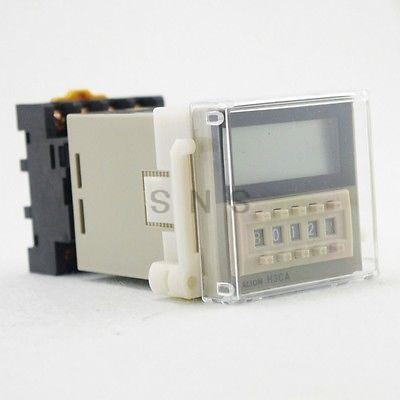
H3CA-A AC24-240V/DC12-240V Time Relay NEW
Description
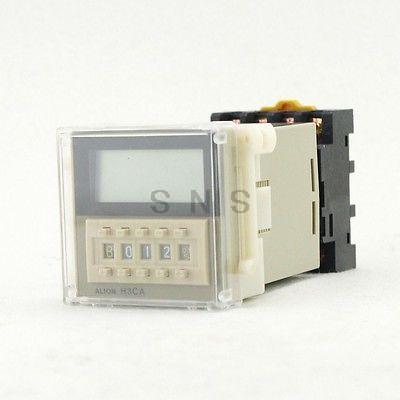
H3CR-A AC220V OMRON Time Relay NEW
OMRON Time Relay H3CR-A AC220V
Product Description:
A wide AC/DC power supply range greatly reduces the number of timer models kept in stock.
A wide range of applications with multiple operating modes, six modes for 11-pin models and four modes for 8-pin models.
Ecological design with reduced current consumption.
Easy sequence checking with instantaneous outputs for a zero set value.
Length of 80 mm or less when panel-mounted with a P3GA-11 Socket (H3CR-A8E, 100 to 240 VAC, 100 to 125 VDC)
PNP input models available.
Standards: UL, CSA, NK, LR, EN 61812-1, and CE Marking.
Specifications:
General | ||||
Item | H3CR-A/-AS | H3CR-AP | H3CR-A8/-A8S | H3CR-A8E |
Operating mode | A: ON-delay | A: ON-delay (power supply start) | ||
B: Flicker OFF start | B2: Flicker ON start (power supply start) | |||
B2: Flicker ON start | E: Interval (power supply start) | |||
C: Signal ON/OFF-delay | J: One-shot (power supply start) | |||
D: Signal OFF-delay |
| |||
E: Interval |
| |||
G: Signal ON/OFF-delay (Only for H3CR-A-300) |
| |||
J: One-shot (Only for H3CR-A-300) |
| |||
Pin type | 11-pin | 8-pin | ||
Input type | No-voltage input | Voltage input | --- | |
Time-limit | H3CR-A/-A8/-AP: Relay output (DPDT) | Relay output (SPDT) | ||
output type | H3CR-AS/-A8S: Transistor output (NPN/PNP universal)* | |||
Instantaneous | --- | Relay output (SPDT) | ||
output type | ||||
Mounting method | DIN track mounting, surface mounting, and flush mounting | |||
Approved standards | UL508, CSA C22.2 No.14, NK, Lloyds | |||
Conforms to EN61812-1 and IEC60664-1 (VDE0110) 4kV/2. | ||||
Output category according to EN60947-5-1 for Timers with Contact Outputs. | ||||
Output category according to EN60947-5-2 for Timers with Transistor Outputs. | ||||
*The internal circuits are optically isolated from the output. This enables universal application as NPN or PNP transistor.
Standard (0.05-s to 300-h) Models | |||||
Time unit | s (sec) | min (min) | h (hrs) | ×10 h (10 hrs) | |
Full scale setting | 1.2 | 0.05 to 1.2 | 0.12 to 1.2 | 1.2 to 12 | |
3 | 0.3 to 3 | 3 to 30 | |||
12 | 1.2 to 12 | 12 to 120 | |||
30 | 3 to 30 | 30 to 300 | |||
Double (0.1-s to 600-h) Models | |||||
Time unit | s (sec) | min (min) | h (hrs) | ×10 h (10 hrs) | |
Full scale setting | 2.4 | 0.1 to 2.4 | 0.24 to 2.4 | 2.4 to 24 | |
6 | 0.6 to 6 | 6 to 60 | |||
24 | 2.4 to 24 | 24 to 240 | |||
60 | 6 to 60 | 60 to 600 | |||
Ratings | |
Rated supply voltage | 100 to 240 VAC (50/60 Hz)/100 to 125 VDC, |
(See notes 1 and 2.) | 24 to 48 VAC (50/60 Hz)/12 to 48 VDC |
| (24 to 48 VAC/VDC for H3CR-A8E) |
| (See note3.) |
Operating voltage range | 85% to 110% of rated supply voltage (90% to 110% at 12 VDC) |
Power reset | Minimum power-opening time: 0.1 s |
Input | No-voltage Input |
ON impedance: 1 kΩ max. | |
ON residual voltage: 1 V max. | |
OFF impedance: 100 kΩ min. | |
| |
Voltage Input | |
Max. permissible capacitance between inputs lines (terminals 6 and 7): 1,200 pF | |
Load connectable in parallel with inputs (terminals 6 and 7). | |
100 to 240 VAC/100 to 125 VDC | |
High (logic) level: 85 to 264 VAC/85 to 137.5 VDC | |
Low (logic) level: 0 to 10 VAC/0 to 10 VDC | |
24 to 48 VAC/12 to 48 VDC | |
High (logic) level: 20.4 to 52.8 VAC/10.8 to 52.8 VDC | |
Low (logic) level: 0 to 2.4 VAC/0 to 1.2 VDC | |
Power consumption | H3CR-A/-A8 |
100 to 240 VAC/100 to 125 VDC | |
(When at 240 VAC, 60 Hz) | |
Relay ON: approx. 2.0 VA (1.6 W) | |
Relay OFF: approx. 1.3 VA (1.1 W) | |
24 to 48 VAC/12 to 48 VDC | |
(When at 24 VDC) | |
Relay ON: approx. 0.8 W | |
Relay OFF: approx. 0.2 W | |
| |
H3CR-AP (See note 3) | |
100 to 240 VAC/100 to 125 VDC | |
(When at 240 VAC, 60 Hz) | |
Relay ON: approx. 2.5 VA (2.2 W) (See note 4.) | |
Relay OFF: approx. 1.8 VA (1.7 W) (See note 4.) | |
24 to 48 VAC/12 to 48 VDC | |
(When at 24 VDC) | |
Relay ON: approx. 0.9 W (See note 4.) | |
Relay OFF: approx. 0.3 W (See note 4.) | |
| |
H3CR-A8E | |
100 to 240 VAC/100 to 125 VDC | |
(When at 240 VAC, 60 Hz) | |
Relay ON/OFF: approx. 2 VA (0.9 W) | |
24 to 48 VAC/VDC | |
(When at 24 VDC) | |
Relay ON/OFF: approx. 0.9 W | |
| |
H3CR-AS/-A8S | |
24 to 48 VAC/12 to 48 VDC | |
(When at 24 VDC) | |
Output ON: 0.3 W Output OFF: 0.2 W | |
Control outputs | Time limit contacts: 5 A at 250 VAC/30 VDC, 0.15 A at 125 VDC, resistive load (cosΦ = 1) |
Transistor output: Open collector (NPN/PNP), 100 mA max. at 30 VDC max., | |
residual voltage: 2 V max. | |
Instantaneous contact: 5 A at 250 VAC/30 VDC, 0.15 A at 125 VDC, resistive load (cosΦ = 1) | |
Note:
1.DC ripple rate: 20% max. (A single-phase, full-wave-rectification power supply can be used).
2.Do not use an inverter output as the power supply.
3.Models with 24-to-48-VAC or 12-to-48-VDC power supply have inrush current. Caution is thus required when turning ON and OFF power to the Timer with a non-contact output from a device such as a sensor. (Models with an inrush current of approximately 50 mA and a 24-VDC power supply are available (the H3CR-A-302 and H3CR-A8-302).)
4.The values are for when the terminals 2 and 7 and terminals 10 and 6 are short-circuited, and include the consumption current of the input circuit.
Characteristics |
|
Accuracy of | ±0.2% FS max. (±0.2%±10 ms max. in a range of 1.2 s or 3 s) |
operating time | |
Setting error | ±5% FS ±50 ms *1 |
Reset time | Min. power-opening time: 0.1 s max. |
Min. pulse width: 0.05 s (H3CR-A/-AS) | |
Reset voltage | 10% max. of rated supply voltage |
Influence of voltage | ±0.2% FS max. (±0.2%±10 ms max. in a range of 1.2 s or 3 s) |
Influence of | ±1% FS max. (±1%±10 ms max. in a range of 1.2 s or 3 s) |
temperature | |
Insulation resistance | 100 MΩ min. (at 500 VDC) |
Dielectric strength | 2,000 VAC (1,000 VAC for H3CR-A[]S), 50/60 Hz for 1 min (between current-carrying metal parts and exposed non-current-carrying metal parts) |
2,000 VAC (1,000 VAC for H3CR-A[]S), 50/60 Hz for 1 min (between control output terminals and operating circuit) | |
2,000 VAC, 50/60 Hz for 1 min (between contacts of different polarities) | |
1,000 VAC, 50/60 Hz for 1 min (between contacts not located next to each other) | |
2,000 VAC, 50/60 Hz for 1 min (between input and control output terminals and operation circuit) for H3CR-AP | |
Impulse withstand | 3 kV (between power terminals) for 100 to 240 VAC/100 to 125 VDC, 1 kV for 24 to 48 VAC/12 to 48 VDC |
voltage | 4.5 kV (between current-carrying terminal and exposed non-current-carrying metal parts) for 100 to 240 VAC/100 to 125 VDC, 1.5 kV for 24 to 48 VAC/12 to 48 VDC and 24 to 48 VAC/VDC |
Noise immunity | ±1.5 kV (between power terminals) and ±600 V (between no-voltage input terminals), square-wave noise by noise simulator (pulse width: 100 ns/1 μs, 1-ns rise) |
Static immunity | Malfunction: 8 kV |
Destruction: 15 kV | |
Vibration resistance | Destruction: 10 to 55 Hz with 0.75-mm single amplitude each in 3 directions for 2 hours each |
Malfunction: 10 to 55 Hz with 0.5-mm single amplitude each in 3 directions for 10 minutes each | |
Shock resistance | Destruction: 1,000 m/s2 3 times each in 6 directions |
Malfunction: 100 m/s2 3 times each in 6 directions | |
Ambient temperature | Operating: -10°C to 55°C (with no icing) |
Storage: -25°C to 65°C (with no icing) | |
Ambient humidity | Operating: 35% to 85% |
Life expectancy | Mechanical: 20,000,000 operations min. (under no load at 1,800 operations/h) |
Electrical: 100,000 operations min. (5 A at 250 VAC, resistive load at 1,800 operations/h) *2 | |
EMC | (EMI): EN61812-1 |
Emission Enclosure: EN55011 Group 1 class A | |
Emission AC Mains: EN55011 Group 1 class A | |
(EMS): EN61812-1 | |
Immunity ESD: IEC61000-4-2: 6 kV contact discharge (level 3), 8 kV air discharge (level 3) | |
Immunity RF-interference from AM Radio Waves: IEC61000-4-3: 10 V/m (80 MHz to 1 GHz) (level 3) | |
Immunity RF-interference from Pulse-modulated Radio Waves: IEC61000-4-3: 10 V/m (900±5 MHz) (level 3) | |
Immunity Conducted Disturbance: IEC61000-4-6: 10 V (0.15 to 80 MHz) (level 3) | |
Immunity Burst: IEC61000-4-4: 2 kV power-line (level 3), 2 kV I/O signal-line (level 4) | |
Immunity Surge: IEC61000-4-5: 1 kV line to line (level 3), 2 kV line to ground (level 3) | |
Case color | Light gray (Munsell 5Y7/1) |
Degree of protection | IP40 (panel surface) |
Weight | Approx. 90 g |
*1.The value is ±5% FS +100 ms to −0 ms max. when the C, D, or G mode signal of the H3CR-AP is OFF.
*2.Refer to Data Sheet.
*3.Relay output only.
H3CR-A AC220V OMRON Time Relay NEWOMRON Time Relay H3CR-A AC220V
Product Description:
A wide AC/DC power supply range greatly reduces the number of timer models kept in stock.
A wide range of applications with multiple operating modes, six modes for 11-pin models and four modes for 8-pin models.
Ecological design with reduced current consumption.
Easy sequence checking with instantaneous outputs for a zero set value.
Length of 80 mm or less when panel-mounted with a P3GA-11 Socket (H3CR-A8E, 100 to 240 VAC, 100 to 125 VDC)
PNP input models available.
Standards: UL, CSA, NK, LR, EN 61812-1, and CE Marking.
Specifications:
General
Item
H3CR-A/-AS
H3CR-AP
H3CR-A8/-A8S
H3CR-A8E
Operating mode
A: ON-delay
A: ON-delay (power supply start)
B: Flicker OFF start
B2: Flicker ON start (power supply start)
B2: Flicker ON start
E: Interval (power supply start)
C: Signal ON/OFF-delay
J: One-shot (power supply start)
D: Signal OFF-delay
E: Interval
G: Signal ON/OFF-delay (Only for H3CR-A-300)
J: One-shot (Only for H3CR-A-300)
Pin type
11-pin
8-pin
Input type
No-voltage input
Voltage input
---
Time-limit
H3CR-A/-A8/-AP: Relay output (DPDT)
Relay output (SPDT)
output type
H3CR-AS/-A8S: Transistor output (NPN/PNP universal)*
Instantaneous
---
Relay output (SPDT)
output type
Mounting method
DIN track mounting, surface mounting, and flush mounting
Approved standards
UL508, CSA C22.2 No.14, NK, Lloyds
Conforms to EN61812-1 and IEC60664-1 (VDE0110) 4kV/2.
Output category according to EN60947-5-1 for Timers with Contact Outputs.
Output category according to EN60947-5-2 for Timers with Transistor Outputs.
*The internal circuits are optically isolated from the output. This enables universal application as NPN or PNP transistor.
Standard (0.05-s to 300-h) Models
Time unit
s (sec)
min (min)
h (hrs)
×10 h (10 hrs)
Full scale setting
1.2
0.05 to 1.2
0.12 to 1.2
1.2 to 12
3
0.3 to 3
3 to 30
12
1.2 to 12
12 to 120
30
3 to 30
30 to 300
Double (0.1-s to 600-h) Models
Time unit
s (sec)
min (min)
h (hrs)
×10 h (10 hrs)
Full scale setting
2.4
0.1 to 2.4
0.24 to 2.4
2.4 to 24
6
0.6 to 6
6 to 60
24
2.4 to 24
24 to 240
60
6 to 60
60 to 600
Ratings
Rated supply voltage
100 to 240 VAC (50/60 Hz)/100 to 125 VDC,
(See notes 1 and 2.)
24 to 48 VAC (50/60 Hz)/12 to 48 VDC
(24 to 48 VAC/VDC for H3CR-A8E)
(See note3.)
Operating voltage range
85% to 110% of rated supply voltage (90% to 110% at 12 VDC)
Power reset
Minimum power-opening time: 0.1 s
Input
No-voltage Input
ON impedance: 1 kΩ max.
ON residual voltage: 1 V max.
OFF impedance: 100 kΩ min.
Voltage Input
Max. permissible capacitance between inputs lines (terminals 6 and 7): 1,200 pF
Load connectable in parallel with inputs (terminals 6 and 7).
100 to 240 VAC/100 to 125 VDC
High (logic) level: 85 to 264 VAC/85 to 137.5 VDC
Low (logic) level: 0 to 10 VAC/0 to 10 VDC
24 to 48 VAC/12 to 48 VDC
High (logic) level: 20.4 to 52.8 VAC/10.8 to 52.8 VDC
Low (logic) level: 0 to 2.4 VAC/0 to 1.2 VDC
Power consumption
H3CR-A/-A8
100 to 240 VAC/100 to 125 VDC
(When at 240 VAC, 60 Hz)
Relay ON: approx. 2.0 VA (1.6 W)
Relay OFF: approx. 1.3 VA (1.1 W)
24 to 48 VAC/12 to 48 VDC
(When at 24 VDC)
Relay ON: approx. 0.8 W
Relay OFF: approx. 0.2 W
H3CR-AP (See note 3)
100 to 240 VAC/100 to 125 VDC
(When at 240 VAC, 60 Hz)
Relay ON: approx. 2.5 VA (2.2 W) (See note 4.)
Relay OFF: approx. 1.8 VA (1.7 W) (See note 4.)
24 to 48 VAC/12 to 48 VDC
(When at 24 VDC)
Relay ON: approx. 0.9 W (See note 4.)
Relay OFF: approx. 0.3 W (See note 4.)
H3CR-A8E
100 to 240 VAC/100 to 125 VDC
(When at 240 VAC, 60 Hz)
Relay ON/OFF: approx. 2 VA (0.9 W)
24 to 48 VAC/VDC
(When at 24 VDC)
Relay ON/OFF: approx. 0.9 W
H3CR-AS/-A8S
24 to 48 VAC/12 to 48 VDC
(When at 24 VDC)
Output ON: 0.3 W Output OFF: 0.2 W
Control outputs
Time limit contacts: 5 A at 250 VAC/30 VDC, 0.15 A at 125 VDC, resistive load (cosΦ = 1)
Transistor output: Open collector (NPN/PNP), 100 mA max. at 30 VDC max.,
residual voltage: 2 V max.
Instantaneous contact: 5 A at 250 VAC/30 VDC, 0.15 A at 125 VDC, resistive load (cosΦ = 1)
Note:
1.DC ripple rate: 20% max. (A single-phase, full-wave-rectification power supply can be used).
2.Do not use an inverter output as the power supply.
3.Models with 24-to-48-VAC or 12-to-48-VDC power supply have inrush current. Caution is thus required when turning ON and OFF power to the Timer with a non-contact output from a device such as a sensor. (Models with an inrush current of approximately 50 mA and a 24-VDC power supply are available (the H3CR-A-302 and H3CR-A8-302).)
4.The values are for when the terminals 2 and 7 and terminals 10 and 6 are short-circuited, and include the consumption current of the input circuit.
Characteristics
Accuracy of
±0.2% FS max. (±0.2%±10 ms max. in a range of 1.2 s or 3 s)
operating time
Setting error
±5% FS ±50 ms *1
Reset time
Min. power-opening time: 0.1 s max.
Min. pulse width: 0.05 s (H3CR-A/-AS)
Reset voltage
10% max. of rated supply voltage
Influence of voltage
±0.2% FS max. (±0.2%±10 ms max. in a range of 1.2 s or 3 s)
Influence of
±1% FS max. (±1%±10 ms max. in a range of 1.2 s or 3 s)
temperature
Insulation resistance
100 MΩ min. (at 500 VDC)
Dielectric strength
2,000 VAC (1,000 VAC for H3CR-A[]S), 50/60 Hz for 1 min (between current-carrying metal parts and exposed non-current-carrying metal parts)
2,000 VAC (1,000 VAC for H3CR-A[]S), 50/60 Hz for 1 min (between control output terminals and operating circuit)
2,000 VAC, 50/60 Hz for 1 min (between contacts of different polarities)
1,000 VAC, 50/60 Hz for 1 min (between contacts not located next to each other)
2,000 VAC, 50/60 Hz for 1 min (between input and control output terminals and operation circuit) for H3CR-AP
Impulse withstand
3 kV (between power terminals) for 100 to 240 VAC/100 to 125 VDC, 1 kV for 24 to 48 VAC/12 to 48 VDC
voltage
4.5 kV (between current-carrying terminal and exposed non-current-carrying metal parts) for 100 to 240 VAC/100 to 125 VDC, 1.5 kV for 24 to 48 VAC/12 to 48 VDC and 24 to 48 VAC/VDC
Noise immunity
±1.5 kV (between power terminals) and ±600 V (between no-voltage input terminals), square-wave noise by noise simulator (pulse width: 100 ns/1 μs, 1-ns rise)
Static immunity
Malfunction: 8 kV
Destruction: 15 kV
Vibration resistance
Destruction: 10 to 55 Hz with 0.75-mm single amplitude each in 3 directions for 2 hours each
Malfunction: 10 to 55 Hz with 0.5-mm single amplitude each in 3 directions for 10 minutes each
Shock resistance
Destruction: 1,000 m/s2 3 times each in 6 directions
Malfunction: 100 m/s2 3 times each in 6 directions
Ambient temperature
Operating: -10°C to 55°C (with no icing)
Storage: -25°C to 65°C (with no icing)
Ambient humidity
Operating: 35% to 85%
Life expectancy
Mechanical: 20,000,000 operations min. (under no load at 1,800 operations/h)
Electrical: 100,000 operations min. (5 A at 250 VAC, resistive load at 1,800 operations/h) *2
EMC
(EMI): EN61812-1
Emission Enclosure: EN55011 Group 1 class A
Emission AC Mains: EN55011 Group 1 class A
(EMS): EN61812-1
Immunity ESD: IEC61000-4-2: 6 kV contact discharge (level 3), 8 kV air discharge (level 3)
Immunity RF-interference from AM Radio Waves: IEC61000-4-3: 10 V/m (80 MHz to 1 GHz) (level 3)
Immunity RF-interference from Pulse-modulated Radio Waves: IEC61000-4-3: 10 V/m (900±5 MHz) (level 3)
Immunity Conducted Disturbance: IEC61000-4-6: 10 V (0.15 to 80 MHz) (level 3)
Immunity Burst: IEC61000-4-4: 2 kV power-line (level 3), 2 kV I/O signal-line (level 4)
Immunity Surge: IEC61000-4-5: 1 kV line to line (level 3), 2 kV line to ground (level 3)
Case color
Light gray (Munsell 5Y7/1)
Degree of protection
IP40 (panel surface)
Weight
Approx. 90 g
*1.The value is ±5% FS +100 ms to −0 ms max. when the C, D, or G mode signal of the H3CR-AP is OFF.
*2.Refer to Data Sheet.
*3.Relay output only.

