| No comment |
Categories
View History
Description
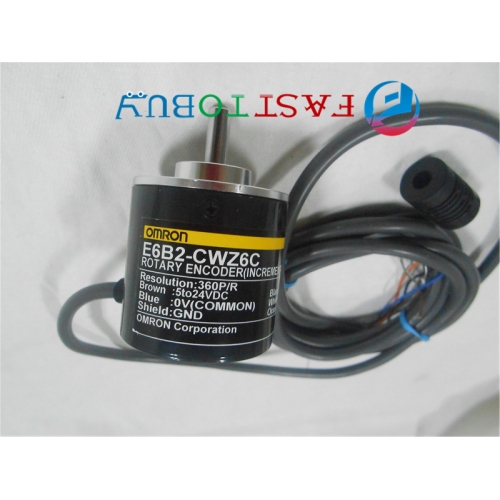
E6C2-CWZ6C 20P/R OMRON encoderEncoder of incremental outer diameter φ50 (Universal)
"Strong" & "simple"
? sealed bearings and realize drip of IP64f, anti-oil
? enhance the resistance axis load performance. Radial 50N thrust to 30N
? wire inclined leads the way. Wire lateral raises and rear raises
? attached to the reverse connection, load short-circuit protection circuit to improve the reliability
(Also available in the linear drive output)
Ratings / Performance
Model
E6C2-CWZ6C
E6C2-CWZ5B
E6C2-CWZ3E
E6C2-CWZ1X
Project
Supply voltage
DC5V-5 ~ 24V +15%
Less than 5% of the pulse (p-p)DC12V-10% ~ 24V +15%
Less than 5% of the pulse (p-p)DC5V—5%?12V+10%
Less than 5% of the pulse (p-p)DC5V ± 5%
Less than 5% of the pulse (p-p)Current consumption * 1
70mA following
80mA following
130mA following
Resolution (pulses / rotation)
10?20?30?40?50?60? 100?200?300?360? 400?500?600?720? 800?1,000?1,024?1,200? 1,500?1,800?2,000
100?200?360?500? 600?1,000?2,000
10?20?30?40?50?60? 100?200?300?360? 400?500?600?1,000? 1,200?1,500?1,800?2,000
10?20?30?40?50?60? 100?200?300?360? 400?500?600?1,000? 1,024?1,200?1,500? 1,800?2,000
Output phase
A?B?Z Phase
A?A?B?B?Z?ZPhase
Output mode
NPN open collector output
PNP open collector output
Voltage output (NPN output)
Linear drive * 2
Output capacity
Below the applied voltage: DC30V
Synchronous current: 35mA max.
Residual voltage: 0.4V
(At sink current of 35mA)Below the applied voltage: DC30V
Synchronous current: 35mA max.
Residual voltage: 0.4V
(At sink current of 35mA)Output resistance: 2kΩ
Synchronous current: 20mA max.
Residual voltage: 0.4V
(At sink current of 20mA)AM26LS31 considerable product
Output current
H: IO =-20mA
L-bit: IS = 20mA
Output voltage VO = 2.5V
VS = 0.5V belowThe highest frequency response *3
100kHz
50kHz
100kHz
Output phase difference
Phase A, B, phase difference of 90 ± 45 ° C (1/4 ± 1/8T)
The output rise and fall time
1μs following
Control the output voltage: 5V
Load resistor 1kΩ
Cable length 2m1μs following
(Cable length: 2m synchronous current: 10mA)0.1μs following
Cable length: 2m
IO =-20mA, IS = 20mAStarting torque
10mN·m following
Moment of inertia
1×10?6kg·m2 following
Shaft allows the force
Radial direction
30N
Axial
20N
Allows the maximum speed
6,000r/min
Protection circuit
Load short-circuit protection, power supply reverse wiring protection
Ambient temperature range
Action: -10 ~ +70 ? save: -25 ~ +85? (with no icing)
Ambient humidity range
Action, save: 35 ~ 85% RH (no condensation)
Insulation resistance
20MΩ or more (500 VDC megger) charging the Ministry of the overall housing
Withstand Voltage
Voltage AC500V 50/60Hz 1min between charging and case
Vibration (durable)
10 ~ 500Hz complex amplitude of 2mm or 150 m/s2, X-, Y, Z each direction scan 11min 3 scan
The impact of (durable)
1,000 m/s2 X, Y,, and Z directions for three times
Protection structure * 3
Enclosure rating IEC IP50
Connection
IEC standard IP64 (JEM specifications IP64f anti-drop · oil) * 4
Material shell
Shell
Sub-lead alloy
Ministry of
the base metalAluminum
Axis
SUS420J2
Weight (packaged)
About 400g
Attachment
Manual
Note? the location of the origin Z phase and the location point of origin as follows.As shown, the D section and the body Z relative to the origin position point to be consistent
Power flowing through the current of about 9A. (Time: about 0.3ms)
* The line driver output is based on the RS-422 data transmission circuit. Long-distance transmission via UTP co-cable.
(AM26LS31 fairly products)
* 3. Electrical response speed according to the resolution of the highest frequency response requirements.
Therefore, when the rotation exceeds the maximum response speed, electrically can not trace the signal.


