| No comment |
Your Position: Home
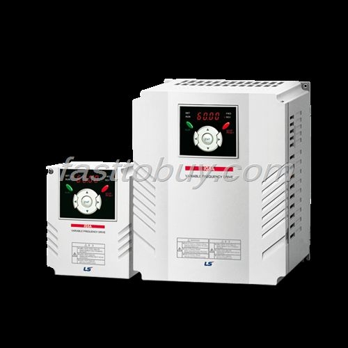
> Control System > Inverter > SV037iG5-4 LS Electrogenesis converter iG5 series NEWCategories
View History
Description
SV037iG5-4 LS Electrogenesis converter iG5 series NEW
If you need more than 10pcs and want to get better wholesale price, please feel free to contact us by following:
email:service@plcage.com
Tel:0086-574-88333153
We will quote you our best price to you in 24hours.
SV004iG5-4 LS Electrogenesis converter iG5 series
Features:
Selectable V/f, sensorless vector control
Motor parameter Auto-tuning
Powerful torque at overall speed range
0.1 ~ 400Hz frequency output
-15% ~ +10% input voltage margin
Fault history: Last 5 faults
0~10Vdc / -10 ~ +10Vdc analog input
IP20 enclosure, UL Type 1 (Option)
Selectable manual/automatic torque boost
Selectable PNP/NPN input signal
2nd motor control and parameter setting
Built-in Dynamic braking transistor as standard
Enhanced process PID control
Built-in RS485 (LS Bus / Modbus RTU) communication
Cooling fan On/Off control & Easy change
Remote control using external keypad * RJ45 cable(Optional)
Upgraded functions:
Sleep & Wake-up (Energy savings)
KEB(Kinetic Energy Buffering) protection
Low leakage PWM algorism
Monitoring & commissioning PC based software tool (Drive View)
Specifications:
1 Phase 200V
SV***iG5A-1*** | 004 | 008 | 015 | |
Max. | (HP) | 0.5 | 1.9 | 2 |
(kW) | 0.4 | 0.75 | 1.5 | |
Output | Capacity (kVA) 2) | 0.95 | 1.9 | 3.0 |
FLA (A) 3) | 2.5 | 5 | 8 | |
Max frequency | 400 [Hz] 4) | |||
Max voltage | 3 phase 200~230V 5) | |||
Input | Rated voltage | 1 phase 200~230 VAC (+10%, -15%) | ||
Rated frequency | 50~60 [Hz] (±5%) | |||
Cooling method | Forced air cooling | |||
Weight (kg) | 0.76 | 1.12 | 1.84 | |
Indicate the maximum applicable motor capacity when using 4 pole LS standard motor.
Rated capacity is based on 220V for 200V series and 440V for 400V series.
Refer to 15-3 of user’s manual when carrier frequency setting (39) is above 3kHz.
Max. frequency setting range is extended to 300Hz when H40 (Control mode select) is set to 3 (Sensorless vector control).
Max. output voltage cannot be higher than the input voltage. It can be programmable below input voltage.
Control | Control method | V/F, Sensorless vector control | ||
Frequency setting resolution | Digital command: 0.01Hz | |||
Frequency accuracy | Digital command: 0.01% of Max. output frequency | |||
V/F pattern | Linear, Squared, User V/F | |||
Overload capacity | 150% per 1 min. | |||
Torque boost | Manual/Auto torque boost | |||
Dynamic | Max. braking | 20% 1) | ||
Max. Duty | 150% when using optional DB resistor 2) | |||
Operation | Operation mode | Keypad/ Terminal/ Communication option/ Remote keypad selectable | ||
Frequency setting resolution | Analog: 0~10V, -10~10V, 0~20mA | |||
Operation features | PID, Up-down, 3-wire | |||
Input | Multi-function | NPN/PNP selectable | ||
FWD/REV RUN, Emergency stop, Fault reset, Jog operation, Multi-step Frequency-High, Mid, Low, | ||||
Output | Open collector | Fault output and | Less than DC 24V, 50mA | |
Multi-function relay | (N.O., N.C.) Less than AC 250V, 1A; Less than DC 30V, 1A | |||
Analog output (AM) | 0~10Vdc (less than 10mA): Output freq, Output current, Output voltage, DC link selectable | |||
Protective | Trip | Over voltage, Under voltage, Over current, Ground fault current detection, Inverter overheat, | ||
Alarm | Stall prevention, Overload | |||
Momentary power loss | Below 15 msec.: Continuous operation (Should be within rated input voltage, rated output power.) | |||
Environ | Protection degree | IP 20, NEMA1 (Optional) | ||
Ambient temp | -10?~50? | |||
Storage temp | -20?~65? | |||
Humidity | Below 90% RH (No condensation) | |||
Altitude/Vibration | Below 1,000m, 5.9m/sec2 (0.6G) | |||
Atmospheric pressure | 70~106 kPa | |||
Location | Protected from corrosive gas, Combustible gas, Oil mist or dust | |||
Means average braking torque during Decel to stop of a motor.
Refer to Chapter 16 of user’s manual for DB resistor specification.
SV037iG5-4 LS Electrogenesis converter iG5 series NEWIf you need more than 10pcs and want to get better wholesale price, please feel free to contact us by following:
email:service@plcage.com
Tel:0086-574-88333153
We will quote you our best price to you in 24hours.SV004iG5-4 LS Electrogenesis converter iG5 series
Features:
Selectable V/f, sensorless vector control
Motor parameter Auto-tuning
Powerful torque at overall speed range
0.1 ~ 400Hz frequency output
-15% ~ +10% input voltage margin
Fault history: Last 5 faults
0~10Vdc / -10 ~ +10Vdc analog input
IP20 enclosure, UL Type 1 (Option)
Selectable manual/automatic torque boost
Selectable PNP/NPN input signal
2nd motor control and parameter setting
Built-in Dynamic braking transistor as standard
Enhanced process PID control
Built-in RS485 (LS Bus / Modbus RTU) communication
Cooling fan On/Off control & Easy change
Remote control using external keypad * RJ45 cable(Optional)
Upgraded functions:
Sleep & Wake-up (Energy savings)
KEB(Kinetic Energy Buffering) protection
Low leakage PWM algorism
Monitoring & commissioning PC based software tool (Drive View)
Specifications:
1 Phase 200V
SV***iG5A-1***
004
008
015
Max.
capacity 1)(HP)
0.5
1.9
2
(kW)
0.4
0.75
1.5
Output
ratingCapacity (kVA) 2)
0.95
1.9
3.0
FLA (A) 3)
2.5
5
8
Max frequency
400 [Hz] 4)
Max voltage
3 phase 200~230V 5)
Input
ratingRated voltage
1 phase 200~230 VAC (+10%, -15%)
Rated frequency
50~60 [Hz] (±5%)
Cooling method
Forced air cooling
Weight (kg)
0.76
1.12
1.84
Indicate the maximum applicable motor capacity when using 4 pole LS standard motor.
Rated capacity is based on 220V for 200V series and 440V for 400V series.
Refer to 15-3 of user’s manual when carrier frequency setting (39) is above 3kHz.
Max. frequency setting range is extended to 300Hz when H40 (Control mode select) is set to 3 (Sensorless vector control).
Max. output voltage cannot be higher than the input voltage. It can be programmable below input voltage.
Control
Control method
V/F, Sensorless vector control
Frequency setting resolution
Digital command: 0.01Hz
Analog command: 0.06Hz (Max. freq.: 60Hz)Frequency accuracy
Digital command: 0.01% of Max. output frequency
Analog command: 0.1% of Max. output frequencyV/F pattern
Linear, Squared, User V/F
Overload capacity
150% per 1 min.
Torque boost
Manual/Auto torque boost
Dynamic
brakingMax. braking
torque20% 1)
Max. Duty
150% when using optional DB resistor 2)
Operation
Operation mode
Keypad/ Terminal/ Communication option/ Remote keypad selectable
Frequency setting resolution
Analog: 0~10V, -10~10V, 0~20mA
Digital: KeypadOperation features
PID, Up-down, 3-wire
Input
Multi-function
terminal
P1-P8NPN/PNP selectable
FWD/REV RUN, Emergency stop, Fault reset, Jog operation, Multi-step Frequency-High, Mid, Low,
Multi-step Accel/Decel-High, Mid, Low, DC braking at stop, 2nd motor select, Frequency UP/Down,
3-wire operation, External trip A, B, PID-Inverter (V/F) operation bypass,
Option-inverter (V/F) operation bypass, Analog Hold, Accel/Decel stopOutput
Open collector
terminalFault output and
inverter status outputLess than DC 24V, 50mA
Multi-function relay
(N.O., N.C.) Less than AC 250V, 1A; Less than DC 30V, 1A
Analog output (AM)
0~10Vdc (less than 10mA): Output freq, Output current, Output voltage, DC link selectable
Protective
functionTrip
Over voltage, Under voltage, Over current, Ground fault current detection, Inverter overheat,
Motor overheat, Output phase open, Overload protection, Communication error,
Loss of speed command, Hardware fault, Fan tripAlarm
Stall prevention, Overload
Momentary power loss
Below 15 msec.: Continuous operation (Should be within rated input voltage, rated output power.)
Above 15 msec.: Auto restart enableEnviron
mentProtection degree
IP 20, NEMA1 (Optional)
Ambient temp
-10?~50?
Storage temp
-20?~65?
Humidity
Below 90% RH (No condensation)
Altitude/Vibration
Below 1,000m, 5.9m/sec2 (0.6G)
Atmospheric pressure
70~106 kPa
Location
Protected from corrosive gas, Combustible gas, Oil mist or dust
Means average braking torque during Decel to stop of a motor.
Refer to Chapter 16 of user’s manual for DB resistor specification.

