| No comment |
Your Position: Home
> Control System > Inverter > VW3A3501 SCHNEIDER Inverter Optional Controller Internal Programmable CardCategories
View History
Description
VW3A3501 SCHNEIDER Inverter Optional Controller Internal Programmable Card
Introduction
By integrating control system functions, "Controller Inside" programmable card (built-in controller) enables the drive to adapt to specific applications.
Sales of Schneider Electric and its partners can be pre-defined set of application software. PS 1131 software for the PC can be used to quickly, completely open the way for programming and debugging new applications. Can not upload the program from the card sent to the PC, so you can protect our proprietary technology.
Altivar 71 drive can be installed only a "Controller Inside" programmable card (built-in controller). It can be used with another combination of an optional card (I / O expansion card or communication card).
(Built-in controller) of the "Controller Inside" programmable card has:
? 10 logic inputs, of which two can be used for 2 counters or 4 of which can be used for 2 incremental encoder
? 2 analog inputs
? six logic output
? 2 analog outputs
? a host port for the CANopen bus
? one for the PS 1131 software for programming the PC port
If the power consumption table does not exceed 200 mA, the "Controller Inside" programmable card (built-in controller) can be powered by the inverter, otherwise you have to use an external 24 VC / DC power supply.
ATV 71WpppN4A24 inverter with a 24-of Vc power supply, allowing the increase to 250mA of power.
"Controller Inside" (built-in controller) programmable card can also be used:
? inverter I / O
? I / O expansion card I / O
? encoder interface card points counter
? The drive parameters (speed, current, torque, etc.
Explain
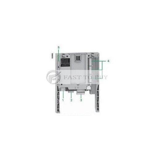
1 ? RJ45 connector to connect the PS 1131 software workshop via an RS485 serial line.
(Including the PowerSuite for PC Connection Kit VW3 A8 106), connected to the PC through a cable and an RS 232/RS 485 adapter.
? 9-pin SUB-D plug-type connector for connection to the CANopen bus.
? with a removable screw terminal connectors, six intervals of 3.81mm contact for 24Vc and four logic input.
4 ? 3 connectors with removable screw terminals, there are six intervals 3.81mm contact for 6 logic inputs, 6 logic outputs, 2 analog inputs, two analog output 2 common point.
5 ? 5 LED, include:
? used to indicate whether the 24 V c power supply
? used to indicate the program is running error
? used to indicate the CANopen bus communication status
? 1 controlled by the application
VW3A3501 SCHNEIDER Inverter Optional Controller Internal Programmable CardIntroduction
By integrating control system functions, "Controller Inside" programmable card (built-in controller) enables the drive to adapt to specific applications.Sales of Schneider Electric and its partners can be pre-defined set of application software. PS 1131 software for the PC can be used to quickly, completely open the way for programming and debugging new applications. Can not upload the program from the card sent to the PC, so you can protect our proprietary technology.
Altivar 71 drive can be installed only a "Controller Inside" programmable card (built-in controller). It can be used with another combination of an optional card (I / O expansion card or communication card).
(Built-in controller) of the "Controller Inside" programmable card has:
? 10 logic inputs, of which two can be used for 2 counters or 4 of which can be used for 2 incremental encoder
? 2 analog inputs
? six logic output
? 2 analog outputs
? a host port for the CANopen bus
? one for the PS 1131 software for programming the PC portIf the power consumption table does not exceed 200 mA, the "Controller Inside" programmable card (built-in controller) can be powered by the inverter, otherwise you have to use an external 24 VC / DC power supply.
ATV 71WpppN4A24 inverter with a 24-of Vc power supply, allowing the increase to 250mA of power.
"Controller Inside" (built-in controller) programmable card can also be used:
? inverter I / O
? I / O expansion card I / O
? encoder interface card points counter
? The drive parameters (speed, current, torque, etc.Explain
1 ? RJ45 connector to connect the PS 1131 software workshop via an RS485 serial line.
(Including the PowerSuite for PC Connection Kit VW3 A8 106), connected to the PC through a cable and an RS 232/RS 485 adapter.
? 9-pin SUB-D plug-type connector for connection to the CANopen bus.
? with a removable screw terminal connectors, six intervals of 3.81mm contact for 24Vc and four logic input.
4 ? 3 connectors with removable screw terminals, there are six intervals 3.81mm contact for 6 logic inputs, 6 logic outputs, 2 analog inputs, two analog output 2 common point.
5 ? 5 LED, include:
? used to indicate whether the 24 V c power supply
? used to indicate the program is running error
? used to indicate the CANopen bus communication status
? 1 controlled by the application

