| No comment |
Your Position: Home
> Transducer/Sensor > Photoelectric Sensors > Photoelectric Switch > VL18L-4P344 SICK Laser Photoelectric switch NEWDescription
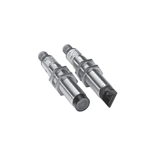
VL18L-4P344 SICK Laser Photoelectric switch NEW
Product Description:
Longest ranges
Detects small parts and switches precisely thank to small laser spot
Laser class 1
A polarisation filter ensures reliable switching even with shiny objects
Specifications:
Scanning range, max. typical/Reflector 0.1 m ... 35 m/P 250 F | |
Operating range 1) | 0.1 m ... 30 m/P 250 F |
Smallest detectable object 1) | Approx. 0.7 mm Ø at 1 m |
Approx. 25 mm Ø at 35 m | |
Light spot diameter | Approx. 9 mm at 35 m |
Angle of dispersion of sender | Approx. 0.04° (SR = max.) |
Approx. 0.02° (SR = 1/2 max.) | |
Light source 2), Light type | Red laser light, 650 nm |
Laser class | Laser class 1 (IEC 60825-1) |
Laser sender output capacity | Max. 0.4 mW |
Housing | Axial optics |
| Radial optics |
Sensitivity setting | Manual, per Teach-in button |
Electronic, per control input C (0 V) 3) | |
Status indicators | Yellow LED: |
Switching output active, reserve | |
LED green: supply voltage VS=ON | |
Supply voltage VS | 10 ... 30 V DC 4) |
Ripple 5) | ≤ 10 % |
Current consumption 6) | ≤ 20 mA |
Switching outputs | Q: PNP |
Q: NPN | |
Output current IA max. | ≤ 100 mA |
Switching mode | Light-/Dark-switching selectable 3) |
Response time 7) | ≤ 0.625 ms |
Switching frequency max. 8) | 800/s |
Connection types | Plug M12, 4-pin |
VDE protection class 9) | ? |
Enclosure rating | IP 67 |
Circuit protection 10) | A, B, C, D |
Ambient temperature | Operation –15 °C ... +55 °C |
Storage –25 °C ... +70 °C | |
Weight | with plug Approx. 60 g |
Housing material | Housing: Nickel-coated brass/PC |
Optics: PC with protective glass pane | |
1) Suitable reflectors for laser photoelectric reflex switches: We recommend our
“F” reflectors with micro triple structure or DG reflector tape for short distances
up to 5 m and our standard reflectors for ranges > 5 m (also see the accessories;
reflectors for VL 18 L)
2) Average service life 100,000 h at TA = +25 °C
3) Controll input C – L.ON/D.ON and – external Teach-in
C = open: light-switching L.ON
C = + VS: dark-switching D.ON
C = 0 V: Sensitivity setting per “external Teach-in”
4) Limit values
5) May not exceed or fall short of VS tolerances
6) Without load
7) Signal transit time with resistive load
8) With light/dark ratio 1:1
9) Reference voltage 50 V
10) A =VS connections reverse-polarity protected
B = Inputs and outputs reverse-polarity protected
C = Interference pulse suppression
D= Outputs overload and short-circuit protected
VL18L-4P344 SICK Laser Photoelectric switch NEWProduct Description:
Longest ranges
Detects small parts and switches precisely thank to small laser spot
Laser class 1
A polarisation filter ensures reliable switching even with shiny objects
Specifications:
Scanning range, max. typical/Reflector 0.1 m ... 35 m/P 250 F
Operating range 1)
0.1 m ... 30 m/P 250 F
Smallest detectable object 1)
Approx. 0.7 mm Ø at 1 m
Approx. 25 mm Ø at 35 m
Light spot diameter
Approx. 9 mm at 35 m
Angle of dispersion of sender
Approx. 0.04° (SR = max.)
Approx. 0.02° (SR = 1/2 max.)
Light source 2), Light type
Red laser light, 650 nm
Laser class
Laser class 1 (IEC 60825-1)
Laser sender output capacity
Max. 0.4 mW
Housing
Axial optics
Radial optics
Sensitivity setting
Manual, per Teach-in button
Electronic, per control input C (0 V) 3)
Status indicators
Yellow LED:
Switching output active, reserve
LED green: supply voltage VS=ON
Supply voltage VS
10 ... 30 V DC 4)
Ripple 5)
≤ 10 %
Current consumption 6)
≤ 20 mA
Switching outputs
Q: PNP
Q: NPN
Output current IA max.
≤ 100 mA
Switching mode
Light-/Dark-switching selectable 3)
Response time 7)
≤ 0.625 ms
Switching frequency max. 8)
800/s
Connection types
Plug M12, 4-pin
VDE protection class 9)
?
Enclosure rating
IP 67
Circuit protection 10)
A, B, C, D
Ambient temperature
Operation –15 °C ... +55 °C
Storage –25 °C ... +70 °C
Weight
with plug Approx. 60 g
Housing material
Housing: Nickel-coated brass/PC
Optics: PC with protective glass pane
1) Suitable reflectors for laser photoelectric reflex switches: We recommend our
“F” reflectors with micro triple structure or DG reflector tape for short distances
up to 5 m and our standard reflectors for ranges > 5 m (also see the accessories;
reflectors for VL 18 L)
2) Average service life 100,000 h at TA = +25 °C
3) Controll input C – L.ON/D.ON and – external Teach-in
C = open: light-switching L.ON
C = + VS: dark-switching D.ON
C = 0 V: Sensitivity setting per “external Teach-in”
4) Limit values
5) May not exceed or fall short of VS tolerances
6) Without load
7) Signal transit time with resistive load
8) With light/dark ratio 1:1
9) Reference voltage 50 V
10) A =VS connections reverse-polarity protected
B = Inputs and outputs reverse-polarity protected
C = Interference pulse suppression
D= Outputs overload and short-circuit protected


