


| No comment |
Your Position: Home
> Control System > PLC > Siemens PLC > 6ES7450-1AP00-0AE0 SIEMENS Counter Module New6ES7450-1AP00-0AE0 SIEMENS Counter Module New
Description
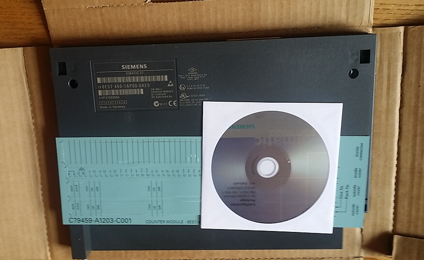
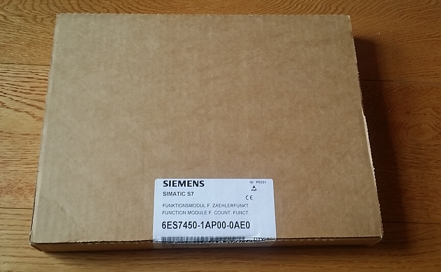
6ES7450-1AP00-0AE0 SIEMENS Counter Module New
SIEMENS Counter Module 6ES7450-1AP00-0AE0
Product Description:
SIMATIC S7-400, FM 450-1 FUNCTION MODULE F. COUNT.FUNCT. WITH 2 CHANNELS INCL. CONFIG. PACKAGE ON CD.
Features:
Supply voltage | |
Load voltage 1L+ | |
Reverse polarity protection | Yes |
Load voltage 2L+ | |
Reverse polarity protection | Yes |
Aux. voltage 1L+, load voltage 2 L+ | |
Rated value (DC) | 24 V |
permissible range, lower limit (DC) | 20.4 V; Dynamic 18.5 V |
permissible range, upper limit (DC) | 28.8 V; dynamic 30.2 V |
non-periodic skip | |
Duration | 500 ms |
Recovery time | 50 s |
Value | 35 V |
Input current | |
from load voltage 1L+ (without load), max. | 40 mA |
from backplane bus 5 V DC, max. | 450 mA |
Encoder supply | |
5 V encoder supply | |
5 V | Yes; 5.2 V +/-2% |
Short-circuit protection | Yes |
Output current, max. | 300 mA |
24 V encoder supply | |
24 V | Yes; 1L+ (-3 V) |
Short-circuit protection | Yes |
Output current, max. | 300 mA |
Power losses | |
Power loss, typ. | 9 W |
Digital inputs | |
Number/binary inputs | 6 |
Functions | 1 for gate start, 1 for gate stop, 1 for setting the counter |
Input voltage | |
for signal "0" | -28.8 to +5 V |
for signal "1" | +11 to +28.8 V |
Input current | |
for signal "1", typ. | 9 mA |
Input delay (for rated value of input voltage) | |
Input frequency (with a time delay of 0.1 ms), max. | 200 kHz |
for standard inputs | |
Parameterizable | Yes |
at "0" to "1", max. | 2.5 µs; >= 2.5 µs (200 kHz); <= 25 µs (20 kHz) |
Digital outputs | |
Number/binary outputs | 6 |
Functionality/short-circuit strength | Yes; Clocked electronically |
Limitation of inductive shutdown voltage to | 2L+ (-39 V) |
Output voltage | |
for signal "0", max. | 3 V |
for signal "1", min. | 2L+ (-1.5 V) |
Output current | |
for signal "1" rated value | 0.5 A |
for signal "1" permissible range for 0 to 60 °C, min. | 5 mA |
for signal "1" permissible range for 0 to 60 °C, max. | 0.6 A |
Output delay with resistive load | |
0 to | 300 µs |
Encoder | |
Connectable encoders | |
Incremental encoder (symmetrical) | Yes; With 2 pulse trains offset by 90° |
Incremental encoder (asymmetrical) | Yes |
24 V initiator | Yes |
24 V directional element | Yes; 1 pulse train, 1 direction level |
Interrupts/diagnostics/status information | |
Status indicator | Yes; 14 green LEDs for status of CR, DIR, inputs and outputs |
Alarms | |
Diagnostic alarm | Yes; Parameterizable |
Hardware interrupt | Yes; Parameterizable |
Diagnostic messages | |
Diagnostic functions | Yes |
Diagnostics | Yes; Diagnostic information readable |
Diagnostics indication LED | |
Description | 2 red LEDs for internal and external errors |
Status indicator digital output (green) | Yes |
Status indicator digital input (green) | Yes |
Counter | |
Number of counter inputs | 2; 32 bit or +/-31 bit |
Counter input 5 V | |
Type | RS 422 |
Terminating resistor | 220 Ω |
Differential input voltage | min. 0.5 V |
Counting frequency, max. | 500 kHz |
Counter input 24 V | |
Input voltage, for signal "0" | -30 to +5 V |
Input voltage, for signal "1" | +11 to +30 V |
Input current, for signal "1", typ. | 9 mA |
Counting frequency, max. | 200 kHz |
Minimum pulse width | >= 2.5 µs (200 kHz); <= 25 µs (20 kHz) (parameterizable) |
Parameter | |
Remark | Assigned binary addresses: 64 bytes/64 bytes |
Galvanic isolation | |
Galvanic isolation digital inputs | |
between the channels and the backplane bus | Yes; Optocoupler |
Galvanic isolation digital outputs | |
between the channels and the backplane bus | Yes; Optocoupler |
Galvanic isolation counter | |
between the channels and the backplane bus | Yes; Optocoupler |
Permissible potential difference | |
between different circuits | 75 VDC / 60 VAC |
Isolation | |
Isolation checked with | 500 V |
Connection method | |
required front connector | 1x 48-pin |
Dimensions | |
Width | 25 mm |
Height | 290 mm |
Depth | 210 mm |
Weight | |
Weight, approx. | 650 g |
6ES7450-1AP00-0AE0 SIEMENS Counter Module NewSIEMENS Counter Module 6ES7450-1AP00-0AE0
Product Description:
SIMATIC S7-400, FM 450-1 FUNCTION MODULE F. COUNT.FUNCT. WITH 2 CHANNELS INCL. CONFIG. PACKAGE ON CD.
Features:
Supply voltage
Load voltage 1L+
Reverse polarity protection
Yes
Load voltage 2L+
Reverse polarity protection
Yes
Aux. voltage 1L+, load voltage 2 L+
Rated value (DC)
24 V
permissible range, lower limit (DC)
20.4 V; Dynamic 18.5 V
permissible range, upper limit (DC)
28.8 V; dynamic 30.2 V
non-periodic skip
Duration
500 ms
Recovery time
50 s
Value
35 V
Input current
from load voltage 1L+ (without load), max.
40 mA
from backplane bus 5 V DC, max.
450 mA
Encoder supply
5 V encoder supply
5 V
Yes; 5.2 V +/-2%
Short-circuit protection
Yes
Output current, max.
300 mA
24 V encoder supply
24 V
Yes; 1L+ (-3 V)
Short-circuit protection
Yes
Output current, max.
300 mA
Power losses
Power loss, typ.
9 W
Digital inputs
Number/binary inputs
6
Functions
1 for gate start, 1 for gate stop, 1 for setting the counter
Input voltage
for signal "0"
-28.8 to +5 V
for signal "1"
+11 to +28.8 V
Input current
for signal "1", typ.
9 mA
Input delay (for rated value of input voltage)
Input frequency (with a time delay of 0.1 ms), max.
200 kHz
for standard inputs
Parameterizable
Yes
at "0" to "1", max.
2.5 µs; >= 2.5 µs (200 kHz); <= 25 µs (20 kHz)
Digital outputs
Number/binary outputs
6
Functionality/short-circuit strength
Yes; Clocked electronically
Limitation of inductive shutdown voltage to
2L+ (-39 V)
Output voltage
for signal "0", max.
3 V
for signal "1", min.
2L+ (-1.5 V)
Output current
for signal "1" rated value
0.5 A
for signal "1" permissible range for 0 to 60 °C, min.
5 mA
for signal "1" permissible range for 0 to 60 °C, max.
0.6 A
Output delay with resistive load
0 to
300 µs
Encoder
Connectable encoders
Incremental encoder (symmetrical)
Yes; With 2 pulse trains offset by 90°
Incremental encoder (asymmetrical)
Yes
24 V initiator
Yes
24 V directional element
Yes; 1 pulse train, 1 direction level
Interrupts/diagnostics/status information
Status indicator
Yes; 14 green LEDs for status of CR, DIR, inputs and outputs
Alarms
Diagnostic alarm
Yes; Parameterizable
Hardware interrupt
Yes; Parameterizable
Diagnostic messages
Diagnostic functions
Yes
Diagnostics
Yes; Diagnostic information readable
Diagnostics indication LED
Description
2 red LEDs for internal and external errors
Status indicator digital output (green)
Yes
Status indicator digital input (green)
Yes
Counter
Number of counter inputs
2; 32 bit or +/-31 bit
Counter input 5 V
Type
RS 422
Terminating resistor
220 Ω
Differential input voltage
min. 0.5 V
Counting frequency, max.
500 kHz
Counter input 24 V
Input voltage, for signal "0"
-30 to +5 V
Input voltage, for signal "1"
+11 to +30 V
Input current, for signal "1", typ.
9 mA
Counting frequency, max.
200 kHz
Minimum pulse width
>= 2.5 µs (200 kHz); <= 25 µs (20 kHz) (parameterizable)
Parameter
Remark
Assigned binary addresses: 64 bytes/64 bytes
Galvanic isolation
Galvanic isolation digital inputs
between the channels and the backplane bus
Yes; Optocoupler
Galvanic isolation digital outputs
between the channels and the backplane bus
Yes; Optocoupler
Galvanic isolation counter
between the channels and the backplane bus
Yes; Optocoupler
Permissible potential difference
between different circuits
75 VDC / 60 VAC
Isolation
Isolation checked with
500 V
Connection method
required front connector
1x 48-pin
Dimensions
Width
25 mm
Height
290 mm
Depth
210 mm
Weight
Weight, approx.
650 g

