| No comment |
Categories
Description
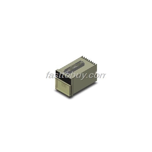
H7AN-4DM AC100-240V OMRON Counter NEW
OMRON Counter H7AN-4DM AC100-240V
Product Description:
72*72 mm , Preset Counter , 2 Digits , With Digital Display
Specifications:
Function | 1 Stage Preset Counter |
Preset stages | 1 stage |
Rated supply voltage | 100 to 240 VAC 50/60 Hz |
Operating voltage range | 85% to 110% of rated supply voltage |
Power consumption | Approx. 10 VA (at 100 VAC) |
External power supply | 12 VDC+-10% 80 mA(permissible ripple: 5%(p-p) max.) |
Counter (Count range) | 0 to 99 |
Counter (Max. counting speed) | 30 Hz |
Minimum counting input signal width: 16.7 ms (ON/OFF ratio: 1:1) | |
Counter (Input mode) | Increment or decrement (switchable) |
Counter (Output modes) | N, F, C, R, K, P, Q |
Counter (One-shot time) | 0.1 to 1 s variable |
Counter (Reset system) | External, manual, automatic and power reset |
Input signal | CP1 ,CP2 ,Reset |
Input method | Voltage input |
No-voltage input (Contact input) | Use a contact which can adequately switch 2.5 mA at 12 V. |
Voltage input | Hight level: 5 to 30 VDC |
Low level: 0 to 2 VDC | |
Input resistance: Approx. 4.7 kOhm | |
Minimum input signal width | External reset: 20 ms |
Manual reset: 20 ms | |
Automatic reset: 100 to 1000ms(C, R, P and Q mode) | |
Power reset: 500 ms | |
Control output (Contact output) | Output type: SPDT |
Switching capacity: 3 A at 250 VAC/30 VDC, resistive load (cos phi=1) | |
Minimum applicable load: 10 mA at 5 VDC (failure level:P reference value) | |
Control output (Solid-state output) | Output type: Transistor output(NPN open collector) |
Output resistance: 1.5 kOhm | |
Switchig capacity: 30 VDC max. 100mA max. | |
Display method | 7-segment with LED display |
Digit | 2 digit |
Character height | Count value: 10 mm (Red) |
Zero suppression: Not equipped | |
Prescaling function | Not provided |
Key protection | Not provided |
Teaching function | Not provided |
Batch counting function | Not provided |
Communications | Not provided |
Memory backup | Not provided |
Surrounding air temperature | Operating: -10 to +55 CEL (With no icing or condensation) |
Storage: -25 to +65 CEL (With no icing or condensation) | |
Ambient humidity | Operating: 35% to 85% |
Storage: 35% to 85% | |
Characteristics | |
Insulation resistance | 100 MOhm min. (at 500 VDC) |
Between current-carrying terminals and exposed non-current-carrying metal parts / Between non-continuous contacts | |
Dielectric withstand voltage | Between current-carrying terminals and exposed non-current-carrying metal parts: 2000 VAC 50/60 Hz for 1 min |
Between non-continuous contacts: 750 VAC 50/60 Hz for 1 min | |
Impulse withstand voltage | Between power terminals: 6.0 kV |
Between current-carrying terminal and exposed non-current -carrying metal parts: 6.0 kV | |
Noise immunity | Between power terminals: +-2k V |
Between input terminals: +-500 V | |
Square-wave noise by noise simulator (Pulse width: 100 ns/1 us, 1-ns rise) | |
Static immunity | +-8 kV (malfunction), +-15 kV (destruction) |
Vibration resistance (Destruction) | 10 to 55 Hz with 0.375 mm single amplitude for two hours each in three directions |
Vibration resistance (Malfunction) | 10 to 55 Hz with 0.25 mm single amplitude for ten minutes each in three directions |
Shock resistance (Destruction) | 300 m/s2 three times each in six directions |
Shock resistance (Malfunction) | 100 m/s2 two times each in six directions |
Mechanical Life expectancy | 10,000,000 operations min. |
Electrical Life expectancy | 100,000 operations min. (3 A at 250 VAC, resistive load) |
Degree of protection | Case front: JEM IP30 |
Applicable standard (UL) | Standard No.: UL508 |
File number: E41515 | |
Applicable standard (CSA) | Standard No.: CSA C22.2 No.14 |
File number: LR22310 | |
Mounting method | Flush mounting |
External connection method | Screw terminals |
Case color | Light gray (Munsell 5Y7/1) |
Attachment | Mounting bracket 2 |
Weight | Approx. 360 g |
H7AN-4DM AC100-240V OMRON Counter NEWOMRON Counter H7AN-4DM AC100-240V
Product Description:
72*72 mm , Preset Counter , 2 Digits , With Digital Display
Specifications:
Function
1 Stage Preset Counter
Preset stages
1 stage
Rated supply voltage
100 to 240 VAC 50/60 Hz
Operating voltage range
85% to 110% of rated supply voltage
Power consumption
Approx. 10 VA (at 100 VAC)
External power supply
12 VDC+-10% 80 mA(permissible ripple: 5%(p-p) max.)
Counter (Count range)
0 to 99
Counter (Max. counting speed)
30 Hz
Minimum counting input signal width: 16.7 ms (ON/OFF ratio: 1:1)
Counter (Input mode)
Increment or decrement (switchable)
Counter (Output modes)
N, F, C, R, K, P, Q
Counter (One-shot time)
0.1 to 1 s variable
Counter (Reset system)
External, manual, automatic and power reset
Input signal
CP1 ,CP2 ,Reset
Input method
Voltage input
No-voltage input (Contact input)
Use a contact which can adequately switch 2.5 mA at 12 V.
Voltage input
Hight level: 5 to 30 VDC
Low level: 0 to 2 VDC
Input resistance: Approx. 4.7 kOhm
Minimum input signal width
External reset: 20 ms
Manual reset: 20 ms
Automatic reset: 100 to 1000ms(C, R, P and Q mode)
Power reset: 500 ms
Control output (Contact output)
Output type: SPDT
Switching capacity: 3 A at 250 VAC/30 VDC, resistive load (cos phi=1)
Minimum applicable load: 10 mA at 5 VDC (failure level:P reference value)
Control output (Solid-state output)
Output type: Transistor output(NPN open collector)
Output resistance: 1.5 kOhm
Switchig capacity: 30 VDC max. 100mA max.
Display method
7-segment with LED display
Digit
2 digit
Character height
Count value: 10 mm (Red)
Zero suppression: Not equipped
Prescaling function
Not provided
Key protection
Not provided
Teaching function
Not provided
Batch counting function
Not provided
Communications
Not provided
Memory backup
Not provided
Surrounding air temperature
Operating: -10 to +55 CEL (With no icing or condensation)
Storage: -25 to +65 CEL (With no icing or condensation)
Ambient humidity
Operating: 35% to 85%
Storage: 35% to 85%
Characteristics
Insulation resistance
100 MOhm min. (at 500 VDC)
Between current-carrying terminals and exposed non-current-carrying metal parts / Between non-continuous contacts
Dielectric withstand voltage
Between current-carrying terminals and exposed non-current-carrying metal parts: 2000 VAC 50/60 Hz for 1 min
Between non-continuous contacts: 750 VAC 50/60 Hz for 1 min
Impulse withstand voltage
Between power terminals: 6.0 kV
Between current-carrying terminal and exposed non-current -carrying metal parts: 6.0 kV
Noise immunity
Between power terminals: +-2k V
Between input terminals: +-500 V
Square-wave noise by noise simulator (Pulse width: 100 ns/1 us, 1-ns rise)
Static immunity
+-8 kV (malfunction), +-15 kV (destruction)
Vibration resistance (Destruction)
10 to 55 Hz with 0.375 mm single amplitude for two hours each in three directions
Vibration resistance (Malfunction)
10 to 55 Hz with 0.25 mm single amplitude for ten minutes each in three directions
Shock resistance (Destruction)
300 m/s2 three times each in six directions
Shock resistance (Malfunction)
100 m/s2 two times each in six directions
Mechanical Life expectancy
10,000,000 operations min.
Electrical Life expectancy
100,000 operations min. (3 A at 250 VAC, resistive load)
Degree of protection
Case front: JEM IP30
Applicable standard (UL)
Standard No.: UL508
File number: E41515
Applicable standard (CSA)
Standard No.: CSA C22.2 No.14
File number: LR22310
Mounting method
Flush mounting
External connection method
Screw terminals
Case color
Light gray (Munsell 5Y7/1)
Attachment
Mounting bracket 2
Weight
Approx. 360 g


