| No comment |
Your Position: Home
> Control System > PLC > Siemens PLC > 253-1AA22-0XA0 Siemens PLC 6ES7 New in boxCategories
View History
Description
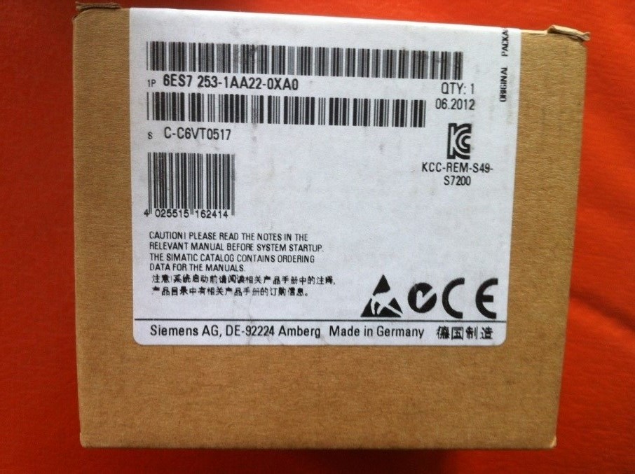
253-1AA22-0XA0 Siemens PLC 6ES7 New in box
Siemens PLC 6ES7 253-1AA22-0XA0
Product Description:
The S7 brings to the user a powerful solution to a host of control applications, which is easy to adapt and expand the system. The S7 is a family of PLC’s which allows the user to tailor their selection of components which best suits their requirements, and is the long term successor to the highly successful S5 range. Whatever the S5 can do, the S7 can do more quickly and more easily.,The 3rd generation of S7-200 now builds on the success of the original range and exploits new CPU’s in order to produce even faster and more powerful range of PLC's. The range of CPU's available has been increased with the introduction of the new 224XP, as has the range of digital, analogue and communications expansion modules.,For the faster type of application real time control is easily achieved by use of the comprehensive range of built-in interrupts. Timed, Communication, High Speed Counter, High Speed Pulse Output, and hardware interrupts are all available, and the implementation of a priority table means that all the interrupts can work simultaneously.,Communications with S7-200 is built in. Inter PLC communications is achieved using two wire network which can be up to 1200 meters and can have up to 126 nodes. In "Freeport" mode the PLC's RS-485 port runs in free ASC11 mode making it possible to communicate with other devices.,In line with Siemens objective to make the programming of S7-200 as user friendly as possible MicroWin programming software has been further improved. These improvements all help minimise program development time. This has been achieved by including more and improving existing "wizards". These help program developers with the more routine/complex parts of their programs, e.g. TD200 configuration, PID loop configuration, High Speed Counter configuration, etc. Inclusion of context sensitive help also means that all the information required is at the users fingertips.
New CPU hardware support provides the option to turn off run mode edit to obtain more program memoryCPU 224XP supports onboard analogue I/O and two communication portsCPU 226 includes additional input filters and pulse catch facility0.22μs processing time per instruction
Modular Expansion up to 256 total I/O (except S7-221)Powerful Instruction Set, and Real Time performanceProgramming via RS-485 comms portAll models have EEPROM memories for user program storage2 or 4 x 30kHz pulse train outputs (dc powered models only )
Specifications:
1. EM 253 Position Module Order Number:
Order Number Expansion Model EM Inputs EM Outputs Removable Connector
6ES7 253--1AA22--0XA0 EM 253 Position Module -- 8 Yes
Eight Q outputs are used as logical controls of the motion function and do not directly control any external signals.
2. EM 253 Position Module General Specifications:
Order Number Module Name and Description Dimensions (mm) (WxHxD) Weight Dissipation VDC Requirements+5 VDC +24 VDC
6ES7 253--1AA22--0XA0 EM 253 Position Module 71.2 x 80 x 62 0.190 kg 2.5 W 190 mA 190 mA
3. EM 253 Position Module Specifications
General 6ES7 253- -1AA22- -0XA0
Input Features
Number of inputs 5 points
Input type
All except ZP Sink/Source (IEC Type 1 sink, except ZP)
ZP Sink only, current limiting for wide voltage range
Input Voltage Maximum Continuous permissible
STP, RPS, LMT+, LMT-- 30 VDC
ZP 30 VDC at 20 mA, maximum
Surge (all inputs) 35 VDC for 0.5 sec.
Rated Value
STP, RPS, LMT+, LMT-- 24 VDC at 4 mA, nominal
ZP 24 VDC at 15 mA, nominal
Logic “1” signal (minimum)
STP, RPS, LMT+, LMT-- 15VDCat2.5mA,minimum
ZP 3 VDC at 8.0 mA, minimum
Logic “0” signal (maximum)
STP, RPS, LMT+, LMT-- 5VDCat1mA,maximum
ZP 1VDCat1mA,maximum
Isolation (field to logic)
Optical Isolation (Galvanic) 500 VAC for 1 minute
Isolation groups of 1 point for STP, RPS, and ZP 2 points for LMT+ and LMT--
Input Delay Times
STP, RPS, LMT+, LMT-- 0.2 ms to 12.8 ms, user selectable
ZP (countable pulse width) 2 µsec minimum
Connection of 2 Wire Proximity Sensor (Bero)
Permissible leakage current 1 mA, maximum
Cable Length Unshielded
STP, RPS, LMT+, LMT-- 30 meters
ZP Not recommended
Shielded
STP, RPS, LMT+, LMT-- 100 meters
ZP 10 meters
Number of inputs on simultaneously All at 55° C (horizontal), All at 45° C(vertical)
Number of integrated outputs 6 points (4 signals)
Output type
P0+, P0--, P1+, P1-- RS422/485 driver
P0, P1, DIS, CLR Open drain
Output voltage
P0, P1, RS--422 drivers, differential output voltage ?
Open circuit 3.5 V typical
Into optocoupler diode with 200? series resistance 2.8 V minimum
100? load 1.5 V minimum
54? load 1.0 V minimum
P0, P1, DIS, CLR open drain
recommended voltage, open circuit 5 VDC, available from module
permissible voltage, open circuit 30 VDC1
Sink current 50 mA maximum
On state resistance 15? maximum
Off state leakage current, 30 VDC 10 µA maximum
Internal Pull up resistor, output drain to T1 3.3K ?2
Output current ?
Number of output groups 1
Outputs on simultaneously All at 55° C (horizontal), All at 45° C(vertical)
Leakage current per point ?
P0, P1, DIS, CLR 10 µA maximum
Overload Protection No
Isolation (field to logic) ?
Optical Isolation (Galvanic) 500 VAC for 1 minute
Output delay
DIS, CLR: Off to On / On to Off 30 µs, maximum
Pulse distortion
P0, P1, outputs, RS--422 drivers, 100 ? external 75 ns maximum
load
P0, P1 outputs, open drain, 5 V / 470 ? external 300 ns maximum
load
Switching frequency
P0+, P0--, P1+, P1--, P0 and P1 200 kHz
Cable length
Unshielded Not recommended
Shielded 10 meters
Power Supply ?
L+ supply voltage 11 to 30 VDC (Class 2, Limited Power, or sensor power from PLC)
Logic supply output +5 VDC +/-- 10%, 200 mA maximum
L l t 5 VDC l d L+ supply current vs. 5 VDC load
Load current 12 VDC Input 24 VDC Input
0 mA (no load) 120 mA 70 mA
200 mA (rated load) 300 mA 130 mA
Isolation ?
L+ power to logic 500 VAC for 1 minute
L+ power to inputs 500 VAC for 1 minute
L+ power to outputs None
Reverse Polarity L+ input and +5V output are diode-protected. Placing a positive voltage on any Mterminal with respect to output point connections can result in potentially damaging current flow.
253-1AA22-0XA0 Siemens PLC 6ES7 New in boxSiemens PLC 6ES7 253-1AA22-0XA0
Product Description:
The S7 brings to the user a powerful solution to a host of control applications, which is easy to adapt and expand the system. The S7 is a family of PLC’s which allows the user to tailor their selection of components which best suits their requirements, and is the long term successor to the highly successful S5 range. Whatever the S5 can do, the S7 can do more quickly and more easily.,The 3rd generation of S7-200 now builds on the success of the original range and exploits new CPU’s in order to produce even faster and more powerful range of PLC's. The range of CPU's available has been increased with the introduction of the new 224XP, as has the range of digital, analogue and communications expansion modules.,For the faster type of application real time control is easily achieved by use of the comprehensive range of built-in interrupts. Timed, Communication, High Speed Counter, High Speed Pulse Output, and hardware interrupts are all available, and the implementation of a priority table means that all the interrupts can work simultaneously.,Communications with S7-200 is built in. Inter PLC communications is achieved using two wire network which can be up to 1200 meters and can have up to 126 nodes. In "Freeport" mode the PLC's RS-485 port runs in free ASC11 mode making it possible to communicate with other devices.,In line with Siemens objective to make the programming of S7-200 as user friendly as possible MicroWin programming software has been further improved. These improvements all help minimise program development time. This has been achieved by including more and improving existing "wizards". These help program developers with the more routine/complex parts of their programs, e.g. TD200 configuration, PID loop configuration, High Speed Counter configuration, etc. Inclusion of context sensitive help also means that all the information required is at the users fingertips.
New CPU hardware support provides the option to turn off run mode edit to obtain more program memoryCPU 224XP supports onboard analogue I/O and two communication portsCPU 226 includes additional input filters and pulse catch facility0.22μs processing time per instruction
Modular Expansion up to 256 total I/O (except S7-221)Powerful Instruction Set, and Real Time performanceProgramming via RS-485 comms portAll models have EEPROM memories for user program storage2 or 4 x 30kHz pulse train outputs (dc powered models only )
Specifications:
1. EM 253 Position Module Order Number:
Order Number Expansion Model EM Inputs EM Outputs Removable Connector
6ES7 253--1AA22--0XA0 EM 253 Position Module -- 8 Yes
Eight Q outputs are used as logical controls of the motion function and do not directly control any external signals.
2. EM 253 Position Module General Specifications:
Order Number Module Name and Description Dimensions (mm) (WxHxD) Weight Dissipation VDC Requirements+5 VDC +24 VDC
6ES7 253--1AA22--0XA0 EM 253 Position Module 71.2 x 80 x 62 0.190 kg 2.5 W 190 mA 190 mA
3. EM 253 Position Module Specifications
General 6ES7 253- -1AA22- -0XA0
Input Features
Number of inputs 5 points
Input type
All except ZP Sink/Source (IEC Type 1 sink, except ZP)
ZP Sink only, current limiting for wide voltage range
Input Voltage Maximum Continuous permissibleSTP, RPS, LMT+, LMT-- 30 VDC
ZP 30 VDC at 20 mA, maximum
Surge (all inputs) 35 VDC for 0.5 sec.
Rated Value
STP, RPS, LMT+, LMT-- 24 VDC at 4 mA, nominal
ZP 24 VDC at 15 mA, nominal
Logic “1” signal (minimum)
STP, RPS, LMT+, LMT-- 15VDCat2.5mA,minimum
ZP 3 VDC at 8.0 mA, minimum
Logic “0” signal (maximum)
STP, RPS, LMT+, LMT-- 5VDCat1mA,maximum
ZP 1VDCat1mA,maximum
Isolation (field to logic)
Optical Isolation (Galvanic) 500 VAC for 1 minute
Isolation groups of 1 point for STP, RPS, and ZP 2 points for LMT+ and LMT--
Input Delay Times
STP, RPS, LMT+, LMT-- 0.2 ms to 12.8 ms, user selectable
ZP (countable pulse width) 2 µsec minimum
Connection of 2 Wire Proximity Sensor (Bero)
Permissible leakage current 1 mA, maximum
Cable Length UnshieldedSTP, RPS, LMT+, LMT-- 30 meters
ZP Not recommended
Shielded
STP, RPS, LMT+, LMT-- 100 meters
ZP 10 meters
Number of inputs on simultaneously All at 55° C (horizontal), All at 45° C(vertical)
Number of integrated outputs 6 points (4 signals)
Output type
P0+, P0--, P1+, P1-- RS422/485 driver
P0, P1, DIS, CLR Open drain
Output voltage
P0, P1, RS--422 drivers, differential output voltage ?
Open circuit 3.5 V typical
Into optocoupler diode with 200? series resistance 2.8 V minimum
100? load 1.5 V minimum
54? load 1.0 V minimum
P0, P1, DIS, CLR open drain
recommended voltage, open circuit 5 VDC, available from module
permissible voltage, open circuit 30 VDC1
Sink current 50 mA maximum
On state resistance 15? maximum
Off state leakage current, 30 VDC 10 µA maximum
Internal Pull up resistor, output drain to T1 3.3K ?2
Output current ?
Number of output groups 1
Outputs on simultaneously All at 55° C (horizontal), All at 45° C(vertical)
Leakage current per point ?
P0, P1, DIS, CLR 10 µA maximum
Overload Protection No
Isolation (field to logic) ?
Optical Isolation (Galvanic) 500 VAC for 1 minute
Output delay
DIS, CLR: Off to On / On to Off 30 µs, maximum
Pulse distortion
P0, P1, outputs, RS--422 drivers, 100 ? external 75 ns maximum
load
P0, P1 outputs, open drain, 5 V / 470 ? external 300 ns maximum
load
Switching frequency
P0+, P0--, P1+, P1--, P0 and P1 200 kHz
Cable length
Unshielded Not recommended
Shielded 10 meters
Power Supply ?
L+ supply voltage 11 to 30 VDC (Class 2, Limited Power, or sensor power from PLC)
Logic supply output +5 VDC +/-- 10%, 200 mA maximum
L l t 5 VDC l d L+ supply current vs. 5 VDC load
Load current 12 VDC Input 24 VDC Input
0 mA (no load) 120 mA 70 mA
200 mA (rated load) 300 mA 130 mA
Isolation ?
L+ power to logic 500 VAC for 1 minute
L+ power to inputs 500 VAC for 1 minute
L+ power to outputs None
Reverse Polarity L+ input and +5V output are diode-protected. Placing a positive voltage on any Mterminal with respect to output point connections can result in potentially damaging current flow.

