| No comment |
Categories
View History
Description
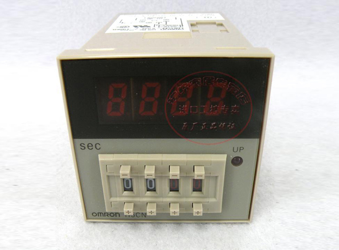
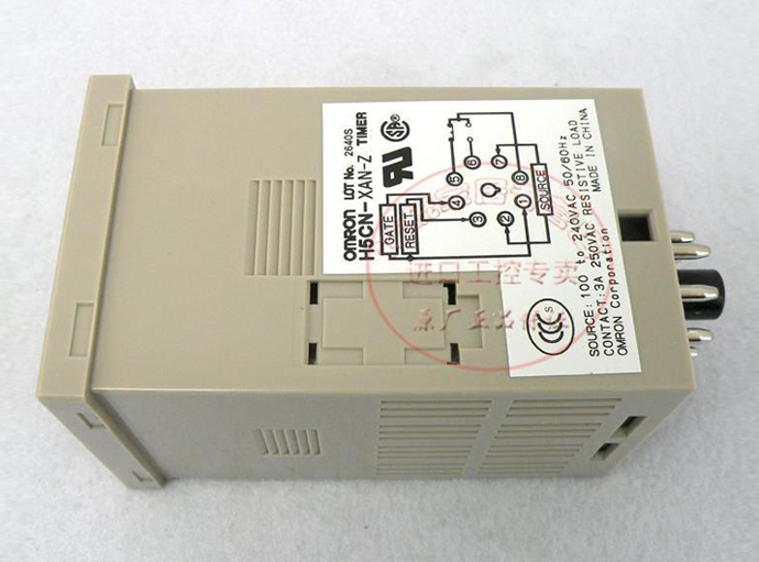
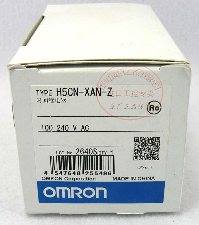
H5CN-XAN-Z AC100-240V OMRON Time Relay NEW
OMRON Time Relay H5CN-XAN-Z AC100-240V
Product Description:
Series version cover a wide range of rated times; 9.999 s, 99.99 s, 999.9 s, 99 min 59 s, and 99 hrs 59 min.
Selection of elapsed time indication, remaining time indication,contact output, and solid-state output types to suit requirements.
Power supply freely selectable within a range of 100 to 240 VAC, as well as 12 to 48 VDC.
Certified for UL and CSA safety standards
Specifications:
Ratings | ||
Item | Contact output | Solid-state output |
Rated supply voltage | 100 to 240 VAC (50/60 Hz), 12 to 48 VDC | 12 to 48 VDC (permissible ripple: 20% max.) |
(permissible ripple: 20% max.) | ||
(See note 1.) | ||
Operating voltage range | 85% to 110% of rated supply voltage | |
Power consumption | Approx. 12 VA at 240 VAC, 50 Hz | Approx. 2.5 W at 48 VDC |
Approx. 2.5 W at 48 VDC | ||
Mounting method | Surface mounting or flush mounting | |
Display | 7-segment LEDs (8-mm-high characters), UP indicator | |
Input method | Contact open and short-circuit input | Open-collector transistor ON/OFF input |
Resetting system and gate input | Reset by power-OFF (See note 2.): | |
min. power OFF time: 0.5 s | ||
External reset or gate (common to contact and solid-state inputs): min. reset input signal width: 0.02 s; | ||
residual voltage: 2 V max. | ||
Output mode | N mode (Power ON-delay) | |
Control outputs | SPDT: 3 A at 250 VAC, resistive load (cosΦ = 1) | Open collector: 100 mA max. at 30 VDC max. |
Ambient temperature | Operating:-10°C to 55°C (with no icing or condensation) | |
Storage:-25°C to 65°C (with no icing or condensation) | ||
Ambient humidity | Operating: 35% to 85% | |
Case color | Light gray (Munsell 5Y7/1) | |
Note:
1.Models with memory backup function are available only for AC power.
2.The H5CN-X[]NM cannot be reset by turning OFF the power.
Characteristics |
|
Accuracy of operating time | ±0.01% ±0.05 s max. (see note 1), ±0.005% ±0.03 s max. (see note 2) (see note 3) |
Setting error | |
Influence of voltage | |
Influence of temperature | |
Insulation resistance | 100 MΩ min. (at 500 VDC) (between current-carrying terminal and exposed non-current carrying metal parts, between power supply circuit and control output circuit) |
Dielectric strength | 2,000 VAC, 50/60 Hz for 1 min (between current-carrying terminal and exposed non-current-carrying metal parts, between power supply circuit and control output circuit) |
Impulse withstand voltage | 6 kV (between power supply terminal) |
6 kV (between current-carrying terminal and exposed non-current carrying metal parts) | |
Noise immunity | Square-wave noise by noise simulator |
AC: ±2 kV (between power supply terminals) | |
DC: ±480 V (between power supply terminals), ±500 V (between input terminals) | |
Static immunity | Malfunction: 8 kV |
Vibration resistance | Destruction:10 to 55 Hz with 0.75-mm single amplitude each in 3 directions for 2 hours each |
Malfunction:10 to 55 Hz with 0.5-mm single amplitude each in 3 directions for 10 minutes each | |
Shock resistance | Destruction:300 m/s2 3 times each in 6 directions |
Malfunction:100 m/s2 3 times each in 6 directions | |
Life expectancy | Mechanical:10,000,000 operations min. |
Electrical:100,000 operations min. (3 A at 250 VAC, resistive load) | |
Approved standards | UL508, CSA C22.2 No. 14 |
Weight | Approx. 200 g |
Note:
1.When timer operation is started by power application.
2.When timer operation is started after a reset input has been applied.
3.These values represent the total accuracy of the timer including the repeat accuracy, setting error, and variation due to voltage and temperature changes. Note that they also comprise errors due to the rise time of the power source and the operating times of the internal and output circuits.
H5CN-XAN-Z AC100-240V OMRON Time Relay NEWOMRON Time Relay H5CN-XAN-Z AC100-240V
Product Description:
Series version cover a wide range of rated times; 9.999 s, 99.99 s, 999.9 s, 99 min 59 s, and 99 hrs 59 min.
Selection of elapsed time indication, remaining time indication,contact output, and solid-state output types to suit requirements.
Power supply freely selectable within a range of 100 to 240 VAC, as well as 12 to 48 VDC.
Certified for UL and CSA safety standards
Specifications:
Ratings
Item
Contact output
Solid-state output
Rated supply voltage
100 to 240 VAC (50/60 Hz), 12 to 48 VDC
12 to 48 VDC (permissible ripple: 20% max.)
(permissible ripple: 20% max.)
(See note 1.)
Operating voltage range
85% to 110% of rated supply voltage
Power consumption
Approx. 12 VA at 240 VAC, 50 Hz
Approx. 2.5 W at 48 VDC
Approx. 2.5 W at 48 VDC
Mounting method
Surface mounting or flush mounting
Display
7-segment LEDs (8-mm-high characters), UP indicator
Input method
Contact open and short-circuit input
Open-collector transistor ON/OFF input
Resetting system and gate input
Reset by power-OFF (See note 2.):
min. power OFF time: 0.5 s
External reset or gate (common to contact and solid-state inputs): min. reset input signal width: 0.02 s;
residual voltage: 2 V max.
Output mode
N mode (Power ON-delay)
Control outputs
SPDT: 3 A at 250 VAC, resistive load (cosΦ = 1)
Open collector: 100 mA max. at 30 VDC max.
Ambient temperature
Operating:-10°C to 55°C (with no icing or condensation)
Storage:-25°C to 65°C (with no icing or condensation)
Ambient humidity
Operating: 35% to 85%
Case color
Light gray (Munsell 5Y7/1)
Note:
1.Models with memory backup function are available only for AC power.
2.The H5CN-X[]NM cannot be reset by turning OFF the power.
Characteristics
Accuracy of operating time
±0.01% ±0.05 s max. (see note 1), ±0.005% ±0.03 s max. (see note 2) (see note 3)
Setting error
Influence of voltage
Influence of temperature
Insulation resistance
100 MΩ min. (at 500 VDC) (between current-carrying terminal and exposed non-current carrying metal parts, between power supply circuit and control output circuit)
Dielectric strength
2,000 VAC, 50/60 Hz for 1 min (between current-carrying terminal and exposed non-current-carrying metal parts, between power supply circuit and control output circuit)
Impulse withstand voltage
6 kV (between power supply terminal)
6 kV (between current-carrying terminal and exposed non-current carrying metal parts)
Noise immunity
Square-wave noise by noise simulator
AC: ±2 kV (between power supply terminals)
DC: ±480 V (between power supply terminals), ±500 V (between input terminals)
Static immunity
Malfunction: 8 kV
Vibration resistance
Destruction:10 to 55 Hz with 0.75-mm single amplitude each in 3 directions for 2 hours each
Malfunction:10 to 55 Hz with 0.5-mm single amplitude each in 3 directions for 10 minutes each
Shock resistance
Destruction:300 m/s2 3 times each in 6 directions
Malfunction:100 m/s2 3 times each in 6 directions
Life expectancy
Mechanical:10,000,000 operations min.
Electrical:100,000 operations min. (3 A at 250 VAC, resistive load)
Approved standards
UL508, CSA C22.2 No. 14
Weight
Approx. 200 g
Note:
1.When timer operation is started by power application.
2.When timer operation is started after a reset input has been applied.
3.These values represent the total accuracy of the timer including the repeat accuracy, setting error, and variation due to voltage and temperature changes. Note that they also comprise errors due to the rise time of the power source and the operating times of the internal and output circuits.

