

Why buy from us?
We offer competitive prices and quality services!
Ask a Question About This Product
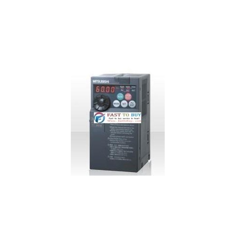
Inverter FR-E720-11KW New in box
Mitsubishi Inverter FR-E720-11KW New in boxMitsubishi Inverter FR-E720-15KWType FR-E720-…K(-C) 8 0.... Read More
$2,101.00
Ex Tax: $2,101.00
- Stock: In Stock
- Model: FR-E720-11KW
- Weight: 9.00kg
1. We typically ship items within three business days after payment is received.
2. Shipping options include DHL, UPS, FedEx, and EMS.
3. Estimated delivery time for express shipping via DHL, UPS, FedEx, or EMS generally ranges from 3 to 10 business days, depending on the destination country.
4. Please verify your address thoroughly when placing your order.
5. Important for buyers: You are responsible for any tariffs on accessories. To potentially avoid these tariffs, you may choose EMS express shipping.
6. The shipping service is responsible for any accidents, delays, or other issues that may arise.
Returns:
We offer a 14-day return policy. If you wish to return an item, please contact us within 14 days and ensure that the package remains unopened. The buyer is responsible for the shipping costs for both the return and the initial delivery, as well as any applicable customs fees. Once we receive and inspect the product, we will process your refund within 24 hours.
For any quality issues that arise during normal use within the warranty period, we will repair the item free of charge. The buyer is responsible for the return shipping cost, while our company will cover the cost of re-shipping the repaired item.
We accept many payments,include Paypal,Bank Transfer etc
Tags:
FR-E720-11KW
Mitsubishi Inverter FR-E720-11KW New in box
Mitsubishi Inverter FR-E720-15KW


