| No comment |
Categories
View History
Description
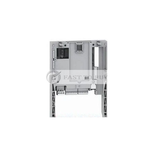
G7F-ADHA LS(LG) Expansion Module New
LS (LG) Expansion Module G7F-ADHA
Product Description:
The G7F-ADHA is A/D·D/A Combination module for use with the GLOFA GM7 and MASTER-K80S series. This module is to convert an analog input signal (voltage or current) from external sensors into a 12-bit signed Binary digital value, and convert digital internal data to analog value (Voltage or Current).
Features:
General Specifications | ||||||
No | Item | Specifications | Standard | |||
1 | Operating temperature | 0 ~ 55? | - | |||
2 | Storage temperature | -25 ~ 75? | ||||
3 | Operating Humidity | 5 ~ 95%RH, non-condensing | ||||
4 | Storage humidity | 5 ~ 95%RH, non-condensing | ||||
5 | Vibration | Occasional vibration | IEC 61131-2 | |||
Frequency | Acceleration | Amplitude | Sweep count | |||
10≤f∠57 Hz | - | 0.075 mm | 10 times in each direction for X, Y, Z | |||
57 ≤f≤150 Hz | 9.8? {1G} | - | ||||
Continuous vibration | ||||||
Frequency | Acceleration | Amplitude | ||||
10≤f∠57 Hz | - | 0.035 mm | ||||
57≤f≤150 Hz | 4.9?{0.5G} | - | ||||
6 | Shocks | *Maximum shock acceleration: 147? {15G} | IEC 61131-2 | |||
*Duration time :11 ms | ||||||
*Pulse wave:half sine wave pulse( 3 times in each of X, Y and Z directions ) | ||||||
7 | Noise immunity | Square wave impulse noise | ±1,500 V | LGIS Standard | ||
Electrostatic discharge | Voltage :4kV(contact discharge) | IEC 61131-2 IEC 1000-4-2 | ||||
Radiated electromagnetic field | 27 ~ 500 MHz, 10 V/m | IEC 61131-2 IEC 1000-4-3 | ||||
Fast transient & burst noise | All power modules | Digital I/Os ( Ue ≥ 24 V) | Digital I/Os (Ue < 24 V) Analog I/Os communication I/Os | IEC 61131-2 IEC 1000-4-4 | ||
2 kV | 1 kV | 0.25 kV | ||||
8 | Atmosphere | Free from corrosive gases and excessive dust | - | |||
9 | Altitude for use | Up to 2,000m | ||||
10 | Pollution degree | 2 or lower | ||||
11 | Cooling method | Self-cooling | ||||
Performance Specification:
Item | Specifications | ||||||
Analog Input | Input Range | Voltage | DC 0∼10V | (input resistance more than 1?) | |||
Current | DC 0∼20? (input resistance 250Ω) | Classified by parameter | |||||
DC 4∼20? (input resistance 250Ω) | |||||||
Digital | Output | 12Bit( -48~4047) | |||||
Voltage/Current Selection | 1.Setting by jumper pin for V/I selection on upper part of product (Up: voltage, Down: Current) 2. Voltage/current selected by the program 3. When current input is used, short the V and I terminal | ||||||
No. of Channel | 2Channels | ||||||
Absolute max. input | Voltage | DC +12V | |||||
Current | DC +24? | ||||||
Analog Output | Output Range | Voltage | DC 0∼10V | (External load resistance 2?∼1?) | |||
Current | DC 0∼20? (External load resistance 510Ω) | Classified by parameter | |||||
DC 4∼20? (External load resistance 510Ω) | |||||||
Digital Input | 12Bit( -48~4047) | ||||||
Voltage/Current Selection | Separated from terminal | ||||||
No. of Channel | 1Channel | ||||||
Absolute max. Output | Voltage | DC +12V | |||||
Current | DC +24? | ||||||
Common | Max. resolution | Voltage | DC0∼10V | 2.5? | (1/4000) | ||
Current | DC0∼20? | 5? | (1/4000 ) | ||||
DC4∼20? | 6.25? | (1/3200 ) | |||||
Accuracy | ±0.5% [Full scale ] |
| |||||
Max. conversion speed | 2?/CH + scan time |
| |||||
Isolation | Photo coupler insulation between I/O terminals and PLC power supply (No isolation between channels) | ||||||
Connect terminals | 9 Points 2 terminals | ||||||
Internal current Consumption | 20? | ||||||
External power supply | DC 21.6 ∼ 26.4V, | 80? | |||||
Weight(g) | 240g |
| |||||
G7F-ADHA LS(LG) Expansion Module NewLS (LG) Expansion Module G7F-ADHA
Product Description:
The G7F-ADHA is A/D·D/A Combination module for use with the GLOFA GM7 and MASTER-K80S series. This module is to convert an analog input signal (voltage or current) from external sensors into a 12-bit signed Binary digital value, and convert digital internal data to analog value (Voltage or Current).
Features:
General Specifications
No
Item
Specifications
Standard
1
Operating temperature
0 ~ 55?
-
2
Storage temperature
-25 ~ 75?
3
Operating Humidity
5 ~ 95%RH, non-condensing
4
Storage humidity
5 ~ 95%RH, non-condensing
5
Vibration
Occasional vibration
IEC 61131-2
Frequency
Acceleration
Amplitude
Sweep count
10≤f∠57 Hz
-
0.075 mm
10 times in each direction for X, Y, Z
57 ≤f≤150 Hz
9.8? {1G}
-
Continuous vibration
Frequency
Acceleration
Amplitude
10≤f∠57 Hz
-
0.035 mm
57≤f≤150 Hz
4.9?{0.5G}
-
6
Shocks
*Maximum shock acceleration: 147? {15G}
IEC 61131-2
*Duration time :11 ms
*Pulse wave:half sine wave pulse( 3 times in each of X, Y and Z directions )
7
Noise immunity
Square wave impulse noise
±1,500 V
LGIS Standard
Electrostatic discharge
Voltage :4kV(contact discharge)
IEC 61131-2 IEC 1000-4-2
Radiated electromagnetic field
27 ~ 500 MHz, 10 V/m
IEC 61131-2 IEC 1000-4-3
Fast transient & burst noise
All power modules
Digital I/Os ( Ue ≥ 24 V)
Digital I/Os (Ue < 24 V) Analog I/Os communication I/Os
IEC 61131-2 IEC 1000-4-4
2 kV
1 kV
0.25 kV
8
Atmosphere
Free from corrosive gases and excessive dust
-
9
Altitude for use
Up to 2,000m
10
Pollution degree
2 or lower
11
Cooling method
Self-cooling
Performance Specification:
Item
Specifications
Analog Input
Input Range
Voltage
DC 0∼10V
(input resistance more than 1?)
Current
DC 0∼20? (input resistance 250Ω)
Classified by parameter
DC 4∼20? (input resistance 250Ω)
Digital
Output
12Bit( -48~4047)
Voltage/Current Selection
1.Setting by jumper pin for V/I selection on upper part of product (Up: voltage, Down: Current) 2. Voltage/current selected by the program 3. When current input is used, short the V and I terminal
No. of Channel
2Channels
Absolute max. input
Voltage
DC +12V
Current
DC +24?
Analog Output
Output Range
Voltage
DC 0∼10V
(External load resistance 2?∼1?)
Current
DC 0∼20? (External load resistance 510Ω)
Classified by parameter
DC 4∼20? (External load resistance 510Ω)
Digital Input
12Bit( -48~4047)
Voltage/Current Selection
Separated from terminal
No. of Channel
1Channel
Absolute max. Output
Voltage
DC +12V
Current
DC +24?
Common
Max. resolution
Voltage
DC0∼10V
2.5?
(1/4000)
Current
DC0∼20?
5?
(1/4000 )
DC4∼20?
6.25?
(1/3200 )
Accuracy
±0.5% [Full scale ]
Max. conversion speed
2?/CH + scan time
Isolation
Photo coupler insulation between I/O terminals and PLC power supply (No isolation between channels)
Connect terminals
9 Points 2 terminals
Internal current Consumption
20?
External power supply
DC 21.6 ∼ 26.4V,
80?
Weight(g)
240g

