| No comment |
Your Position: Home
> Control System > PLC > Other PLC > PLC 24VDC 8 DI 8 DO transistor Main Unit VIGOR VH-16MT-DI NewCategories
View History
Description
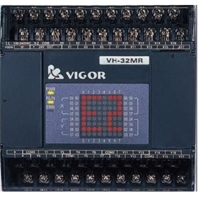
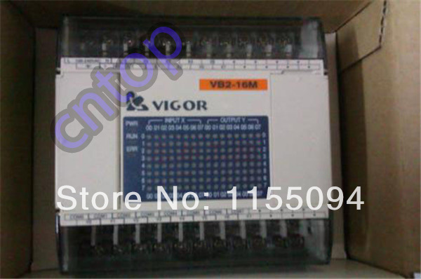
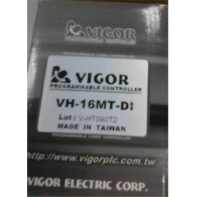
VH-16MT-DI PLC VIGOR 24VDC 8 point input 8 point output Connector Original brand new
Functional specification
Item | Specifications | |||||
Operation Control Method | Cyclic Operation by Stored Program | |||||
Programming Language | Electric Ladder Diagram + SFC | |||||
1/0 Control Method | Batch Processing | |||||
Operation Processing Time | Basic Instruction | 0.375 -12.56J1S | ||||
Applied Instruction | Several JlS- Several100 flS | |||||
Memory Capacity (Flash ROM) | Program Capacity | Built-in 4 K Steps Flash ROM | ||||
Comment Capacity | 2730 comments (16 characters or 8 Chinese characters for each comment) | |||||
Program Comment Capacity | 20,000 characters or 10,000 Chinese characters | |||||
Max. Input I Output Points | 128 points: XO-X77, YO- Y77 | |||||
Internal Relay | Auxiliary Coil (M) | General | 384 points: MO- M383 | |||
Latched | 128 points: M384- M511 | |||||
Special | 256 points: M9000- M9255 | |||||
State Coil (S) | Initial | 10 points: SO- S9 (Latched) | ||||
Latched | 118 points: S10 -S127 | |||||
Timer (T) | 100mS | 63 points: TO- T62 (Timer range: 0.1-3276.7 sec.) | ||||
10mS | 31 points: T32- T62 (Timer range: 0.01-327.67 sec.), when the coil M9028= "ON" | |||||
1 ms | 1 points: T63 (Timer range: 0.001 - 32.767 sec.) | |||||
Counter (C) | 16-bit U | General | 16 points: CO- C15 | |||
Latched | 16points: C16-C31 | |||||
High Speed Counter (C) | 32-bit Up/Down | 1-phase Counter | 11 points: C235 - C245 (Signal Frequency: 10KHz Max.) | |||
2-phase Counter | 5 points: C246- C250 (Signal Frequency: 10 KHz Max.) | |||||
A/B Phase Counter | 4 points: C251 - C254 (Signal Frequency: 5 KHz Max.) | |||||
Data Register (D) | General | 128 points: DO- D127 | ||||
Latched | 128 points: D128- D255 | |||||
Special | 256 points: D9000 - D9255 | |||||
Index | 16 points: VO- V7, ZO- Z7 | |||||
Level | Branch Level (P) | 64 points: PO - P63 | ||||
Interrupt Level (I) | 15 points: 6 points for external interrupt, 3 points for timer interrupt, and 6 points for counter interrupt | |||||
Nest Level (N) | 8 points: NO- N7 | |||||
Constants | Decimal (K) | 16 Bits | -32768 - 32767 | |||
32 Bits | -2147483648-2147483647 | |||||
Hexadecimal (H) | 16 Bits | OH- FFFFH | ||||
32 Bits | OH- FFFFFFFFH | |||||
Pulse Output | 1 point; Max. 7 KHz | |||||
Programming Device Link Interface CP1 | RS-232C, available direct connect to a computer, HMI or MODEM | |||||
Communication Link Interface CP2 (Optional) | RS-232C or RS-422 I RS-485, available direct connect to a computer, HMI or MODEM | |||||
Communication Link Interface CP3 (Optional) | RS-485, available direct connect to a computer, HMI | |||||
Real Time Clock (Optional) | To indicates year, month, day, hour, min., sec. and week | |||||
Error Code Display Function | Displays 109 error codes (01-99 and EO-E9) | |||||
Analog Potentiometer | 2 Analog Potentiometers, each one can be seating as 0255 | |||||
VH-16MT-DI PLC VIGOR 24VDC 8 point input 8 point output Connector Original brand new
Functional specification
Item
Specifications
Operation Control Method
Cyclic Operation by Stored Program
Programming Language
Electric Ladder Diagram + SFC
1/0 Control Method
Batch Processing
Operation
Processing Time
Basic Instruction
0.375 -12.56J1S
Applied Instruction
Several JlS- Several100 flS
Memory Capacity (Flash ROM)
Program Capacity
Built-in 4 K Steps Flash ROM
Comment Capacity
2730 comments (16 characters or 8 Chinese characters for each comment)
Program Comment Capacity
20,000 characters or 10,000 Chinese characters
Max. Input I Output Points
128 points: XO-X77, YO- Y77
Internal
Relay
Auxiliary Coil
(M)
General
384 points: MO- M383
Latched
128 points: M384- M511
Special
256 points: M9000- M9255
State Coil
(S)
Initial
10 points: SO- S9 (Latched)
Latched
118 points: S10 -S127
Timer
(T)
100mS
63 points: TO- T62 (Timer range: 0.1-3276.7 sec.)
10mS
31 points: T32- T62 (Timer range: 0.01-327.67 sec.), when the coil M9028= "ON"
1 ms
1 points: T63 (Timer range: 0.001 - 32.767 sec.)
Counter
(C)
16-bit U
General
16 points: CO- C15
Latched
16points: C16-C31
High Speed
Counter (C)
32-bit Up/Down
1-phase Counter
11 points: C235 - C245 (Signal Frequency: 10KHz Max.)
2-phase Counter
5 points: C246- C250 (Signal Frequency: 10 KHz Max.)
A/B Phase Counter
4 points: C251 - C254 (Signal Frequency: 5 KHz Max.)
Data Register
(D)
General
128 points: DO- D127
Latched
128 points: D128- D255
Special
256 points: D9000 - D9255
Index
16 points: VO- V7, ZO- Z7
Level
Branch Level (P)
64 points: PO - P63
Interrupt Level (I)
15 points: 6 points for external interrupt, 3 points for timer interrupt, and 6 points for counter interrupt
Nest Level (N)
8 points: NO- N7
Constants
Decimal
(K)
16 Bits
-32768 - 32767
32 Bits
-2147483648-2147483647
Hexadecimal
(H)
16 Bits
OH- FFFFH
32 Bits
OH- FFFFFFFFH
Pulse Output
1 point; Max. 7 KHz
Programming Device Link Interface CP1
RS-232C, available direct connect to a computer, HMI or MODEM
Communication Link Interface CP2 (Optional)
RS-232C or RS-422 I RS-485, available direct connect to a computer, HMI or MODEM
Communication Link Interface CP3 (Optional)
RS-485, available direct connect to a computer, HMI
Real Time Clock (Optional)
To indicates year, month, day, hour, min., sec. and week
Error Code Display Function
Displays 109 error codes (01-99 and EO-E9)
Analog Potentiometer
2 Analog Potentiometers, each one can be seating as 0255

