| No comment |
Your Position: Home
> Control System > PLC > Delta PLC > DVP04AD-E2 Delta PLC 4 point 14-bit resolution Analog I/O Module Original brand newCategories
Description
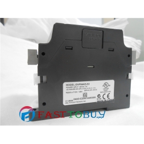
DVP04AD-E2 Delta PLC 4 point 14-bit resolution Analog I/O Module Original brand new
Introduction
DVP04AD-E2 analog input module receives external 4 points of analog input signals (voltage or current) and converts them into 16-bit digital signals. You can select voltage input or current input by the wiring. In addition, you can access the data in the module by applying FROM/TO instructions or read the average value of channels directly by using MOV instruction (Please refer to allocation of special registers D9900 ~ D9999).
Electrical Specifications
Analog / Digital module (04A/D) | |
Power supply voltage | 24VDC (20.4VDC ~ 28.8VDC) (-15% ~ +20%) |
Max. rated power consumption | 1W, supplied by external power source |
Connector | European standard removable terminal block (Pin pitch: 5mm) |
Operation/storage temperature | Operation: 0°C~55°C (temp.), 5~95% (humidity), Pollution degree2 Storage: -25°C~70°C (temp.), 5~95% (humidity) |
Vibration/shock immunity | International standards: IEC61131-2, IEC 68-2-6 (TEST Fc)/ IEC61131-2 & IEC 68-2-27 (TEST Ea) |
Series connection to DVP-PLC MPU | The modules are numbered from 0 to 7 automatically by their distance from MPU. Max. 8 modules are allowed to connect to MPU and will not occupy any digital I/O points. |
Functions
Analog / Digital module | Voltage input | Current input | |||
Analog input channel | 4 channels / each module | ||||
Range of analog input | +-10V | +-5V | +-20mA | 0 ~ 20mA | 4 ~ 20mA |
Range of digital conversion | +-32,000 | +-32,000 | +-32,000 | 0 ~ 32,000 | 0 ~ 32,000 |
Max./Min. range of digital data | +-32,384 | +-32,384 | +-32,384 | -384~+32,384 | -384~+32,384 |
Hardware Resolution | 14 bits | 14 bits | 14 bits | 13 bits | 13 bits |
Input impedance | >=1M? | 250? | |||
Range of absolute input | +-15V | +-32mA | |||
Overall accuracy | +-0.5% when in full scale (25°C, 77°F) +-1% when in full scale within the range of 0 ~ 55°C (32 ~ 131°F) | ||||
Response time | 400us / each channel | ||||
Digital data format | 2’s complement of 16 bits | ||||
Average function | Supported. Available for setting up sampling range in CR#8 ~ CR#11. Range: K1 ~ K100. | ||||
Self-diagnosis | Upper and lower bound detection in all channels | ||||
Isolation method | Optical coupler isolation between digital circuits and analog circuits. No isolation among analog channels. 500VDC between digital circuits and Ground 500VDC between analog circuits and Ground 500VDC between analog circuits and digital circuits 500VDC between 24VDC and Ground | ||||
Product Profile & Dimension
DVP04AD-E2 Delta PLC 4 point 14-bit resolution Analog I/O Module Original brand new
Introduction
DVP04AD-E2 analog input module receives external 4 points of analog input signals (voltage or current) and converts them into 16-bit digital signals. You can select voltage input or current input by the wiring. In addition, you can access the data in the module by applying FROM/TO instructions or read the average value of channels directly by using MOV instruction (Please refer to allocation of special registers D9900 ~ D9999).
Electrical Specifications
Analog / Digital module (04A/D)
Power supply voltage
24VDC (20.4VDC ~ 28.8VDC) (-15% ~ +20%)
Max. rated power
consumption
1W, supplied by external power source
Connector
European standard removable terminal block (Pin pitch: 5mm)
Operation/storage
temperature
Operation: 0°C~55°C (temp.), 5~95% (humidity), Pollution degree2
Storage: -25°C~70°C (temp.), 5~95% (humidity)
Vibration/shock
immunity
International standards: IEC61131-2, IEC 68-2-6 (TEST Fc)/
IEC61131-2 & IEC 68-2-27 (TEST Ea)
Series connection to
DVP-PLC MPU
The modules are numbered from 0 to 7 automatically by their distance from MPU. Max. 8 modules are allowed to connect to MPU and will not occupy any digital I/O points.
Functions
Analog / Digital module
Voltage input
Current input
Analog input channel
4 channels / each module
Range of analog input
+-10V
+-5V
+-20mA
0 ~ 20mA
4 ~ 20mA
Range of digital
conversion
+-32,000
+-32,000
+-32,000
0 ~ 32,000
0 ~ 32,000
Max./Min. range of
digital data
+-32,384
+-32,384
+-32,384
-384~+32,384
-384~+32,384
Hardware Resolution
14 bits
14 bits
14 bits
13 bits
13 bits
Input impedance
>=1M?
250?
Range of absolute input
+-15V
+-32mA
Overall accuracy
+-0.5% when in full scale (25°C, 77°F)
+-1% when in full scale within the range of 0 ~ 55°C (32 ~ 131°F)
Response time
400us / each channel
Digital data format
2’s complement of 16 bits
Average function
Supported. Available for setting up sampling range in CR#8 ~
CR#11. Range: K1 ~ K100.
Self-diagnosis
Upper and lower bound detection in all channels
Isolation method
Optical coupler isolation between digital circuits and analog circuits.
No isolation among analog channels.
500VDC between digital circuits and Ground
500VDC between analog circuits and Ground
500VDC between analog circuits and digital circuits
500VDC between 24VDC and Ground
Product Profile & Dimension

