

Why buy from us?
We offer competitive prices and quality services!
Ask a Question About This Product
- Stock: In Stock
- Model: E6A2-CS5C
- Weight: 0.04kg
2. Shipping options include DHL, UPS, FedEx, and EMS.
3. Estimated delivery time for express shipping via DHL, UPS, FedEx, or EMS generally ranges from 3 to 10 business days, depending on the destination country.
4. Please verify your address thoroughly when placing your order.
5. Important for buyers: You are responsible for any tariffs on accessories. To potentially avoid these tariffs, you may choose EMS express shipping.
6. The shipping service is responsible for any accidents, delays, or other issues that may arise.
Returns:
We offer a 14-day return policy. If you wish to return an item, please contact us within 14 days and ensure that the package remains unopened. The buyer is responsible for the shipping costs for both the return and the initial delivery, as well as any applicable customs fees. Once we receive and inspect the product, we will process your refund within 24 hours.
For any quality issues that arise during normal use within the warranty period, we will repair the item free of charge. The buyer is responsible for the return shipping cost, while our company will cover the cost of re-shipping the repaired item.
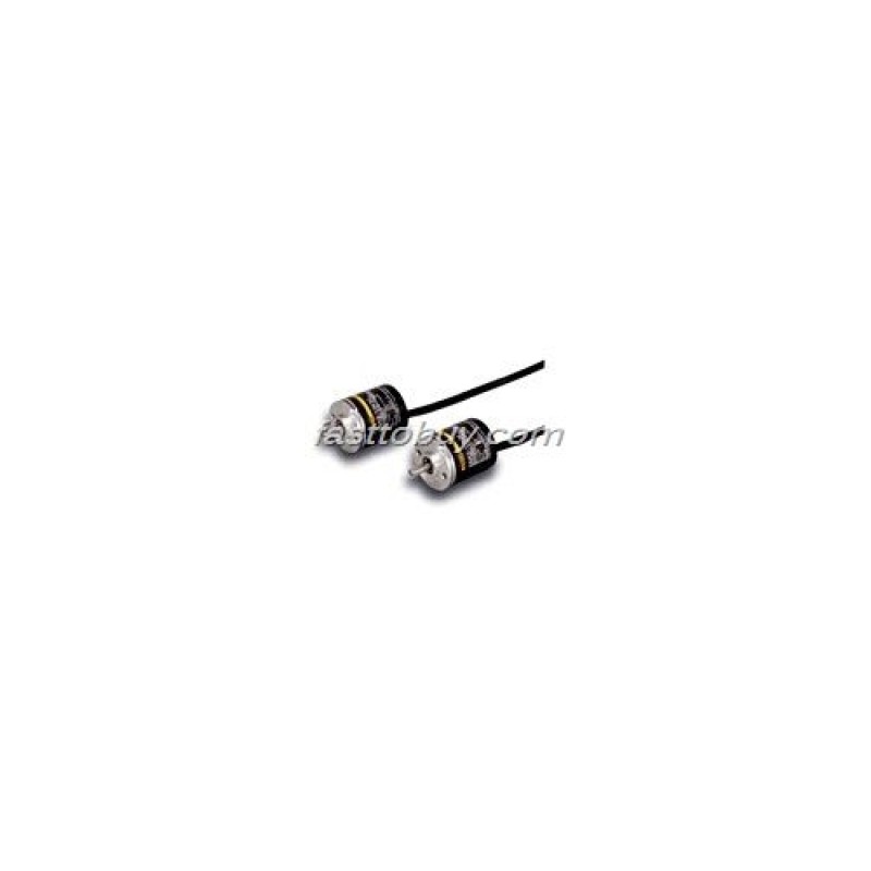
Incremental outer diameter φ25 encoder
Small encoder (outer diameter φ25)
? adapt to the needs of the positioning. Equipped with the origin of the output phase (Z)-type.
? the size of the outer diameter of φ25, with a resolution of 500P / R products.
Ratings / Performance:
Model | E6A2-CS3E | E6A2-CS3C | E6A2-CS5C | E6A2-CW3E | E6A2-CW3C | E6A2-CW5C | E6A2-CWZ3E | E6A2-CWZ3C | E6A2-CWZ5C | |
Project | ||||||||||
Supply voltage | DC5V—5%? 12V+10% Pulsation(p-p)5% following | DC12V— 10%? 24V+15% Pulsation (p-p)5% following | DC5V—5%? 12V+10% Pulsation(p-p)5% following | DC12V— 10%? 24V+15% Pulsation (p-p)5% following | DC5V—5%? 12V+10% Pulsation(p-p)5% following | DC12V— 10%? 24V+15% Pulsation (p-p)5% following | ||||
Current consumption * 1 | 30mA following | 20mA following | 0mA following | 20mA following | 50mA following | 30mA following | ||||
Resolution (pulses / rotation) | 10?20?60?100?200?300?360? 500 | 100?200?360?500 | ||||||||
Output phase | APhase A Phase | BPhase A Phase | BPhase .Z Phase | |||||||
Output state | Voltage output | Open collector output | Voltage output | Open collector output | Voltage output | Open collector output | ||||
Output capacity | Output Resistance: 2kΩ output current: 20mA Residual voltage: 0.4V below the output current of 20 mA | Plus synchronize the following voltage: DC30V Current: 30mA Residual voltage: 0.4V below (at sink current of 30mA) | Output Resistance: 2kΩ output current: 20mA Residual voltage: 0.4V below the output current of 20 mA | Plus synchronize the following voltage: DC30V Current: 30mA Residual voltage: 0.4V below (at sink current of 30mA) | Output Resistance: 2kΩ output current: 20mA Residual voltage: 0.4V below the output current of 20 mA | Plus synchronize the following voltage: DC30V Current: 30mA Residual voltage: 0.4V below (at sink current of 30mA) | ||||
The highest frequency response * 2 | 30kHz | |||||||||
Output phase difference | —— | Phase A, B, phase difference 90 ° ± 45 ° | ||||||||
Output load ratio | 50±25% | —— | ||||||||
The output rise and fall time | 1.0μs less wire length of 500mm, the synchronous current 10mA | 1.0μs less wire length 500mm, to control the output voltage of 5V, load resistance 1kΩ | 1.0μs less wire length of 500mm, the synchronous current 10mA | 1.0μs less wire length 500mm, to control the output voltage of 5V, load resistance 1kΩ | 1.0μs less wire length of 500mm, the synchronous current 10mA | 1.0μs less wire length 500mm, to control the output voltage of 5V, load resistance 1kΩ | ||||
Starting torque | 1mN·m following | |||||||||
Moment of inertia | 1×10?7kg·m2 following | |||||||||
Shaft allows the force | Radial direction | 10N | ||||||||
Axial | 5N | |||||||||
Allows the maximum speed | 5,000r/min | |||||||||
Ambient temperature range | Operating: -10 ~ +55 ? save: -25 ~ +80 ? (with no icing) | |||||||||
Ambient humidity range | Work, save: 35 ~ 85% RH (no condensation) | |||||||||
Insulation resistance | 20MΩ or more (500 VDC megger) charging the Ministry of the overall housing | |||||||||
Withstand Voltage | Voltage AC500V 50/60Hz 1min between charging and case | |||||||||
Vibration (durable) | The upper and lower amplitude 10 ~ 55Hz 1.5mm X, Y, Z each direction 2h | |||||||||
The impact of (durable) | 500 m/s2 X-, Y, and Z directions for three times | |||||||||
Protection structure * 3 | Enclosure rating IEC IP50 | |||||||||
Material shell | Shell | Aluminum alloy | ||||||||
Ministry of | Aluminum | |||||||||
Axis | SUS420J2 | |||||||||
Installation of | Iron ferrous zinc plated | |||||||||
Weight (packaged) | About 35g | |||||||||
Attachment |
| |||||||||
* 1 When power flows through the red flow of about 9A.(Time: about 0.3m)
* (2) the maximum electrical response speed of the provisions of the resolution and the highest response frequency.
The maximum response frequency of the electrical speed (r / min) = (the maximum frequency response / resolution) × 60
Therefore, when the rotation exceeds the maximum response speed, electrically can not trace the signal.
* 3 for water, oil was not protective.


