

Why buy from us?
We offer competitive prices and quality services!
Ask a Question About This Product
- Stock: In Stock
- Model: E6B2-CWZ6C
- Weight: 0.10kg
2. Shipping options include DHL, UPS, FedEx, and EMS.
3. Estimated delivery time for express shipping via DHL, UPS, FedEx, or EMS generally ranges from 3 to 10 business days, depending on the destination country.
4. Please verify your address thoroughly when placing your order.
5. Important for buyers: You are responsible for any tariffs on accessories. To potentially avoid these tariffs, you may choose EMS express shipping.
6. The shipping service is responsible for any accidents, delays, or other issues that may arise.
Returns:
We offer a 14-day return policy. If you wish to return an item, please contact us within 14 days and ensure that the package remains unopened. The buyer is responsible for the shipping costs for both the return and the initial delivery, as well as any applicable customs fees. Once we receive and inspect the product, we will process your refund within 24 hours.
For any quality issues that arise during normal use within the warranty period, we will repair the item free of charge. The buyer is responsible for the return shipping cost, while our company will cover the cost of re-shipping the repaired item.
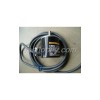
Incremental outer diameter φ40 encoder
the generic type of φ40
? corresponds to the power supply voltage DC5 ~ 24V
(Open collector output)
? The outer diameter of φ40 equipped with the resolution of 2000P / R
? with the origin position Z is relatively simplistic display
? shaft load, radial 30N thrust to 20N
? attached to the reverse connection, load short-circuit protection circuit to improve the reliability
(Also available in the linear drive output)
Model | E6B2-CWZ6C | E6B2-CWZ5B | E6B2-CWZ3E | E6B2-CWZ1X | |
Project | |||||
Supply voltage | DC5V-5 ~ 24V +15% | DC12V-10% ~ 24V +15% | DC5V-12V to +10% | DC5V ± 5% | |
Current consumption * 1 | 70mA following | 80mA following | 130mA following | ||
Resolution (pulses / rotation) | 10?20?30?40?50?60? | 100?200?360?500? | 10?20?30?40?50?60? | 10?20?30?40?50?60? | |
Output phase | A?B?Z Phase | A?A?B?B?Z?ZPhase | |||
Output phase difference | Phase A, B, phase difference of 90 ± 45 ° C (1/4 ± 1/8T) | ||||
Output mode | NPN open collector output | PNP open collector output | Voltage output (NPN output) | Linear drive * 2 | |
Output capacity | Below the applied voltage: DC30V | Below the applied voltage: DC30V | Output resistance: 2kΩ | AM26LS31 considerable product | |
The highest frequency response *3 | 100kHz | 50kHz | 100kHz | ||
The output rise and fall time | 1μs following | 1μs following | 0.1μs following | ||
Starting torque | 0.98mN·m following | ||||
Moment of inertia | 1×10?6kg·m2 following | ||||
Shaft allows the force | Radial direction | 30N | |||
Axial | 20N | ||||
Allows the maximum speed | 6,000r/min | ||||
Protection circuit | Load short-circuit protection, power supply reverse wiring protection | ||||
Ambient temperature range | Action: -10 ~ +70 ? save: -25 ~ +85? (with no icing) | ||||
Ambient humidity range | Action, save: 35 ~ 85% RH (no condensation) | ||||
Insulation resistance | 20MΩ or more (500 VDC megger) charging the Ministry of the overall housing | ||||
Withstand Voltage | Voltage AC500V 50/60Hz 1min between charging and case | ||||
Vibration (durable) | 10 ~ 500Hz complex amplitude of 2mm or 150 m/s2, X-, Y, Z each direction scan 11min 3 scan | ||||
The impact of (durable) | 1,000 m/s2 X, Y,, and Z directions for three times | ||||
Protection structure * 3 | Enclosure rating IEC IP50 | ||||
Connection | Pre-wired (standard cable length 500mm) | ||||
Material shell | Shell | ABS | |||
Ministry of | Aluminum | ||||
Axis | SUS420J2 | ||||
Weight (packaged) | About 100g | ||||
Attachment | Coupling, hex wrench, manual | ||||
* 1 When power flows through the red flow of about 9A.(Time: about 0.3ms)
* The line driver output is based on the RS-422A data transmission circuit, through the double-stranded wire hunt for long-distance transmission. (Built-in AM26LS31 fairly products)
* 3. Electricity highest response speed according to the resolution and the highest response frequency requirements.
Therefore, when the rotation exceeds the maximum response speed, electrically can not trace the signal.


