| No comment |
Categories
View History
Description
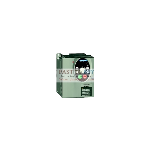
ATV31HU30N4A Schneider Inverter New in box
Product Description:
The Altivar 31 is designed to make industrial and commercial machines more efficient while at the same time, simplifying its integration into a single control system architecture. With the highest overtorque and the only drive with a remote graphic keypad in its class, the Altivar 31 is ideally suited for a variety of machines
Available Ratings
•0.25 - 3 HP, 200/240 VAC, single-phase input
•0.25 - 20 HP, 200/240 VAC, three-phase input
•0.5 - 20 HP, 380/500 VAC, three-phase input
•1 - 20 HP, 575/600 VAC, three-phase input
Open Communication
The Altivar 31 comes standard with integrated communication ports for Modbus and CANopen networks and optional cards for CANopen Daisy Chain, DeviceNet, Profibus DP.
Ultra Reliable
The Altivar 31 comes with coated cards (IEC 60721-3-3 Classes 3C2 and 3S2) and can withstand temperatures ranging from -10° C to 50° C without derating, even when installed side-by-side. Its integrated EMC (electro-magnetic compatibility) also minimizes power disturbances and electrical interference.
Easy to Setup
Autotuning, multi-loaders and 50 pre-loaded application functions to manage common facility processes make setup and installation a breeze. The user friendly user interface built into the drive provides intuitive navigation and speed control with the dial as well as local start/stop control. Other options such as a remote graphical keypad and Bluetooth capability further enhance your ability to optimize machine control from day one.
Features?
Degree of protection | • IP20 without protective vent cover, NEMA 1, UL open type • IP21 on wiring terminals • IP31 and IP41 all other areas • UL Type 1 without removal of the protective vent cover from the top of the controller and with the addition of the Conduit Entry Kit. |
Resistance to vibration | Conforming to IEC/EN 60068-2-6: 1.5 mm peak to peak from 3 to 13 Hz, 1 gn from 13 to 150 Hz |
Resistance to shock | 15 g for 11 ms conforming to IEC/EN 60068-2-27 |
Pollution degree | Pollution degree 2 according to UL 840. Protect the drive against dust, corrosive gas, and falling liquid. |
Maximum relative humidity | 96% maximum, non-condensing and without dripping (provide heating system if there is condensation) Conforms to IEC 60068-2-3 |
Maximum ambient temperature | Storage: -13 to +158 ° F (-25 to +70 ° C) Operation: +14 to +122 ° F (-10 to +50 ° C) without vent cover removed and without derating; +14 to +140 ° F (-10 to +60 ° C) with vent cover removed and with derating. Refer to derating curves on page 30. |
Altitude | Up to 3,300 ft (1,000 m) without derating; derate by 1% for each additional 330 ft (100 m) |
Operating position Maximum permanent angle in relation to the normal vertical mounting position |
|
Input voltage | ATV31••••M2 (1 phase): 200 V -15% to 240 V +10% ATV31••••M3X (3 phase): 200 V -15% to 240 V +10% ATV31••••N4 (3 phase): 380 V -15% to 460 V +15% ATV31••••S6X (3 phase): 525 V -15% to 575 V +15% |
Input frequency | 50/60 Hz ±5% |
Input phases | ATV31••••M2: 1 ATV31••••M3X: 3 ATV31••••N4: 3 ATV31••••S6X: 3 |
Output voltage | Maximum voltage equal to input voltage |
Output frequency | 0 to 500 Hz |
Output phases | 3 |
Speed range | 1:50 |
Transient overtorque | 170–200% nominal motor torque (typical value) |
Maximum transient current | Up to 150% of nominal drive controller current for 60 seconds |
Braking torque | With braking resistor: 100% of nominal motor torque continuously and up to 150% for 60 s. Without braking resistor: • Drive controllers ≥ ATV31•U22••: 30% of nominal motor torque • Drive controllers ≤ ATV31•U15••: 50% of nominal motor torque • Drive controllers ≤ATV31•075••: 100% of nominal motor torque • Drive controllers ≤ ATV31•018M2: 150% of nominal motor torque |
Frequency resolution | Display: 0.1 Hz Analog inputs: 0.1 Hz to 100 Hz maximum [(high speed – low speed)/1024] |
Switching frequency | Adjustable from 2.0 kHz to 16 kHz. Randomly modulated by default, but this can be disabled. |
Drive controller protection | Galvanic isolation between power and control (power supplies, inputs, outputs) Protection against short circuits: • within internal power supplies • between output phases • between output phases and ground Protection against input phase loss Thermal protection against overheating and overcurrents Undervoltage and overvoltage faults Overbraking fault |
Motor protection | Thermal protection, integrated into the drive controller, by I2t calculation Protection against motor phase loss |
Internal supplies available | Short-circuit and overload protection: One +10 V (-0 / +8%) supply for setpoint potentiometer (2.2 to 10 kΩ), maximum current 10 mA One +24 V supply (minimum 19 V, maximum 30 V) for logic inputs, maximum current 100 mA |
Configurable analog inputs Three configurable analog inputs AI1, AI2, AI3. | AI1: Analog input 0 to +10 V (maximum safe voltage is 30 V) • Impedance: 30 kΩ • Resolution: 0.01 V, 10-bit converter • Precision: ± 4.3% of maximum value • Linearity: ± 0.2% of maximum value • Sampling time: 8 ms • Shielded cable length: 100 m (328 ft) maximum AI2: Analog input 0 to +10 V (maximum safe voltage is 30 V) Bipolar analog input 0 to ±10 V (maximum safe voltage is ±30 V) The + or - polarity of the voltage on AI2 affects the direction of the setpoint and therefore the direction of rotation. • Impedance: 30 kΩ • Resolution: 0.01 V, 10-bit + sign converter • Precision: ± 4.3% of maximum value • Linearity: ± 0.2% of maximum value • Sampling time: 8 ms • Shielded cable length: 100 m (328 ft) maximum AI3: Analog input X–Y mA; X and Y programmable from 0–20 mA • Impedance: 250 Ω • Resolution: 0.02 mA, 10-bit converter • Precision: ± 4.3% of maximum value • Linearity: ± 0.2% of maximum value • Sampling time: 8 ms |
Analog output configurable for | Analog output 0 to 10 V, minimum load impedance 470 Ω |
voltage, current, or logic output | or Analog output X to Y mA; X and Y programmable from 0–20 mA, maximum load impedance 800 Ω: |
Analog voltage output AOV | • Resolution: 8 bits |
or | • Precision: ± 1% |
Analog current output AOC | • Linearity: ± 0.2% |
or | • Sampling time: 8 ms |
Logic voltage output on AOC | or |
Can assign either AOV or AOC, but not both. | AOC can be configured as a 24 V logic output with a minimum load impedance of 1.2 kΩ. |
Configurable relay outputs |
|
R1A is a N.O. contact. | • Minimum switching capacity: 10 mA for 5 Vdc |
R1B is a N.C. contact. | • Maximum switching capacity on a resistive load (power factor = 1 and L/R time constant = 0 ms): |
R1C is the common. | 5 A for 250 Vac and 30 Vdc |
R1 is programmable—factory set as a fault | • Maximum switching capacity on an inductive load (power factor = 0.4 and L/R time constant = 7 ms): |
relay (R1A is closed and R1B is open when the | 1.5 A for 250 Vac and 30 Vdc |
controller is powered with no fault) | • Sampling time: 8 ms |
R2A, R2C | • Service life: 100,000 operations at maximum switching power; |
N.O. contact of programmable relay R2 | 1,000,000 operations at minimum switching power |
Logic inputs LI | Programmable logic inputs • +24 V power supply (maximum 30 V) • Impedance: 3.5 kΩ |
LI1, LI2, LI3, LI4, LI5, LI6 | • State 0 if the difference between LIx and CLI is < 5 V, State 1 if the difference between LIx and CLI is > 11 V • Sampling time: 4 ms |
Maximum I/O connection capacity and tightening torque | 14 AWG (2.5 mm2) 0.6 N•m (5.31 lb-in) |
Acceleration and deceleration ramps | Ramp profiles: • linear, can be adjusted separately from 0.1 to 999.9 s • S, U, or customized Automatic adaptation of deceleration ramp time if braking capacities are exceeded, possible inhibition of this adaptation (use of braking resistor). |
DC injection braking | DC injection braking can be initiated: • By a signal on a programmable logic input • Automatically as soon as the estimated output frequency drops to < 0.5 Hz, period adjustable from 0 to 30 s or continuous, current adjustable from 0 to 1.2 In |
Signaling on the drive local keypad display | • One red LED indicating the presence of drive voltage • Four 7-segment displays • Two CANopen status LEDs (RUN and ERR) |
Scan time for reference change | 5 ms |
ATV31HU30N4A Schneider Inverter New in boxProduct Description:
The Altivar 31 is designed to make industrial and commercial machines more efficient while at the same time, simplifying its integration into a single control system architecture. With the highest overtorque and the only drive with a remote graphic keypad in its class, the Altivar 31 is ideally suited for a variety of machines
Available Ratings
•0.25 - 3 HP, 200/240 VAC, single-phase input
•0.25 - 20 HP, 200/240 VAC, three-phase input
•0.5 - 20 HP, 380/500 VAC, three-phase input
•1 - 20 HP, 575/600 VAC, three-phase input
Open Communication
The Altivar 31 comes standard with integrated communication ports for Modbus and CANopen networks and optional cards for CANopen Daisy Chain, DeviceNet, Profibus DP.
Ultra Reliable
The Altivar 31 comes with coated cards (IEC 60721-3-3 Classes 3C2 and 3S2) and can withstand temperatures ranging from -10° C to 50° C without derating, even when installed side-by-side. Its integrated EMC (electro-magnetic compatibility) also minimizes power disturbances and electrical interference.
Easy to Setup
Autotuning, multi-loaders and 50 pre-loaded application functions to manage common facility processes make setup and installation a breeze. The user friendly user interface built into the drive provides intuitive navigation and speed control with the dial as well as local start/stop control. Other options such as a remote graphical keypad and Bluetooth capability further enhance your ability to optimize machine control from day one.
Features?
Degree of protection
• IP20 without protective vent cover, NEMA 1, UL open type • IP21 on wiring terminals • IP31 and IP41 all other areas • UL Type 1 without removal of the protective vent cover from the top of the controller and with the addition of the Conduit Entry Kit.
Resistance to vibration
Conforming to IEC/EN 60068-2-6: 1.5 mm peak to peak from 3 to 13 Hz, 1 gn from 13 to 150 Hz
Resistance to shock
15 g for 11 ms conforming to IEC/EN 60068-2-27
Pollution degree
Pollution degree 2 according to UL 840. Protect the drive against dust, corrosive gas, and falling liquid.
Maximum relative humidity
96% maximum, non-condensing and without dripping (provide heating system if there is condensation) Conforms to IEC 60068-2-3
Maximum ambient temperature
Storage: -13 to +158 ° F (-25 to +70 ° C) Operation: +14 to +122 ° F (-10 to +50 ° C) without vent cover removed and without derating; +14 to +140 ° F (-10 to +60 ° C) with vent cover removed and with derating. Refer to derating curves on page 30.
Altitude
Up to 3,300 ft (1,000 m) without derating; derate by 1% for each additional 330 ft (100 m)
Operating position Maximum permanent angle in relation to the normal vertical mounting position
Input voltage
ATV31••••M2 (1 phase): 200 V -15% to 240 V +10% ATV31••••M3X (3 phase): 200 V -15% to 240 V +10% ATV31••••N4 (3 phase): 380 V -15% to 460 V +15% ATV31••••S6X (3 phase): 525 V -15% to 575 V +15%
Input frequency
50/60 Hz ±5%
Input phases
ATV31••••M2: 1 ATV31••••M3X: 3 ATV31••••N4: 3 ATV31••••S6X: 3
Output voltage
Maximum voltage equal to input voltage
Output frequency
0 to 500 Hz
Output phases
3
Speed range
1:50
Transient overtorque
170–200% nominal motor torque (typical value)
Maximum transient current
Up to 150% of nominal drive controller current for 60 seconds
Braking torque
With braking resistor: 100% of nominal motor torque continuously and up to 150% for 60 s. Without braking resistor: • Drive controllers ≥ ATV31•U22••: 30% of nominal motor torque • Drive controllers ≤ ATV31•U15••: 50% of nominal motor torque • Drive controllers ≤ATV31•075••: 100% of nominal motor torque • Drive controllers ≤ ATV31•018M2: 150% of nominal motor torque
Frequency resolution
Display: 0.1 Hz Analog inputs: 0.1 Hz to 100 Hz maximum [(high speed – low speed)/1024]
Switching frequency
Adjustable from 2.0 kHz to 16 kHz. Randomly modulated by default, but this can be disabled.
Drive controller protection
Galvanic isolation between power and control (power supplies, inputs, outputs) Protection against short circuits: • within internal power supplies • between output phases • between output phases and ground Protection against input phase loss Thermal protection against overheating and overcurrents Undervoltage and overvoltage faults Overbraking fault
Motor protection
Thermal protection, integrated into the drive controller, by I2t calculation Protection against motor phase loss
Internal supplies available
Short-circuit and overload protection: One +10 V (-0 / +8%) supply for setpoint potentiometer (2.2 to 10 kΩ), maximum current 10 mA One +24 V supply (minimum 19 V, maximum 30 V) for logic inputs, maximum current 100 mA
Configurable analog inputs Three configurable analog inputs AI1, AI2, AI3.
AI1: Analog input 0 to +10 V (maximum safe voltage is 30 V) • Impedance: 30 kΩ • Resolution: 0.01 V, 10-bit converter • Precision: ± 4.3% of maximum value • Linearity: ± 0.2% of maximum value • Sampling time: 8 ms • Shielded cable length: 100 m (328 ft) maximum AI2: Analog input 0 to +10 V (maximum safe voltage is 30 V) Bipolar analog input 0 to ±10 V (maximum safe voltage is ±30 V) The + or - polarity of the voltage on AI2 affects the direction of the setpoint and therefore the direction of rotation. • Impedance: 30 kΩ • Resolution: 0.01 V, 10-bit + sign converter • Precision: ± 4.3% of maximum value • Linearity: ± 0.2% of maximum value • Sampling time: 8 ms • Shielded cable length: 100 m (328 ft) maximum AI3: Analog input X–Y mA; X and Y programmable from 0–20 mA • Impedance: 250 Ω • Resolution: 0.02 mA, 10-bit converter • Precision: ± 4.3% of maximum value • Linearity: ± 0.2% of maximum value • Sampling time: 8 ms
Analog output configurable for
Analog output 0 to 10 V, minimum load impedance 470 Ω
voltage, current, or logic output
or Analog output X to Y mA; X and Y programmable from 0–20 mA, maximum load impedance 800 Ω:
Analog voltage output AOV
• Resolution: 8 bits
or
• Precision: ± 1%
Analog current output AOC
• Linearity: ± 0.2%
or
• Sampling time: 8 ms
Logic voltage output on AOC
or
Can assign either AOV or AOC, but not both.
AOC can be configured as a 24 V logic output with a minimum load impedance of 1.2 kΩ.
Configurable relay outputs
R1A is a N.O. contact.
• Minimum switching capacity: 10 mA for 5 Vdc
R1B is a N.C. contact.
• Maximum switching capacity on a resistive load (power factor = 1 and L/R time constant = 0 ms):
R1C is the common.
5 A for 250 Vac and 30 Vdc
R1 is programmable—factory set as a fault
• Maximum switching capacity on an inductive load (power factor = 0.4 and L/R time constant = 7 ms):
relay (R1A is closed and R1B is open when the
1.5 A for 250 Vac and 30 Vdc
controller is powered with no fault)
• Sampling time: 8 ms
R2A, R2C
• Service life: 100,000 operations at maximum switching power;
N.O. contact of programmable relay R2
1,000,000 operations at minimum switching power
Logic inputs LI
Programmable logic inputs • +24 V power supply (maximum 30 V) • Impedance: 3.5 kΩ
LI1, LI2, LI3, LI4, LI5, LI6
• State 0 if the difference between LIx and CLI is < 5 V, State 1 if the difference between LIx and CLI is > 11 V • Sampling time: 4 ms
Maximum I/O connection capacity and tightening torque
14 AWG (2.5 mm2) 0.6 N•m (5.31 lb-in)
Acceleration and deceleration ramps
Ramp profiles: • linear, can be adjusted separately from 0.1 to 999.9 s • S, U, or customized Automatic adaptation of deceleration ramp time if braking capacities are exceeded, possible inhibition of this adaptation (use of braking resistor).
DC injection braking
DC injection braking can be initiated: • By a signal on a programmable logic input • Automatically as soon as the estimated output frequency drops to < 0.5 Hz, period adjustable from 0 to 30 s or continuous, current adjustable from 0 to 1.2 In
Signaling on the drive local keypad display
• One red LED indicating the presence of drive voltage • Four 7-segment displays • Two CANopen status LEDs (RUN and ERR)
Scan time for reference change
5 ms

