| No comment |
Your Position: Home
> Control System > Module > Kinco > PLC CPU AC220V 14 DI 10 DO relay KINCO K306-24AR NewDescription
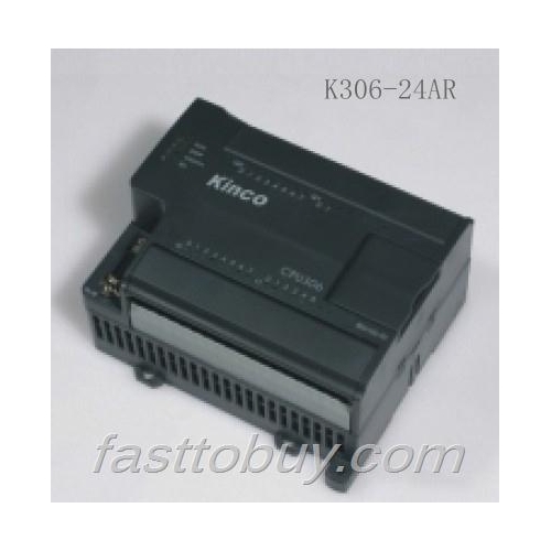
Kinco K3 PLC CPU Module CPU306 Series K306-24AR NIB 14 Digital Inputs 10 Relay Outputs AC85~265V NewIf you need more than 10pcs and want to get better wholesale price, please feel free to contact us by following:
email:[email protected]
Tel:0086-574- 88333153
We will quote you our best price to you in 24hours.Specifications:
Model
CPU306
K306-24DT
K306-24AT
K306-24DR
K306-24AR
Technical Specification
CPU
16-Bit Industrial
Execution Speed
Typical Bool Instruction Time: <0.5μS
Word Operation Time: <48μS
Arithmetic Operation Time for Integers: <65μS
Arithmetic Operation Time for Floating Points: <150μS
DI Points
14XDC24V
DO Points
10XDC24V
10XRelay
User Program Memory
FRAM, 8KB/About 1,200 Steps
Program Backup
Permanent Storage, Without the Need of Battery
Memory Area
Variable Storage Area (V Area): 4KB
System Storage Area (SM Area): 300 Bytes
Internal Storage Area (M Area): 32 Bytes
Data Retention Characteristic
Configure with the Programming Software: V Area, C (Counter) Area
Retention Mode and Period
Adopt Super Capacitors and Support a Retention Period of not Less than 144 Hours Upon Power Failure Under Normal Temperature.
Data Backup Characteristic
Perform Backup Operations VB3648~VB3902 According to User Instructions, 255 Bytes in Total
Backup Mode and Time
FRAM, 255 Bytes in Total (Writing Operation for 10 Billion Times), Permanent Backup
Floating Points
Supported; the Whole V Area can be Used for Floating Points
Programming Language Supported
Ladder Drawing (LD), Instruction List (IL)
Instruction Set
Basic Instructions: 55; Expansion Instructions: 252
Password Protection
Yes
Max. I/O
Digital Data: 88 in Total (64 DI and 64 DO Respectively);
Analog Data: 16 in Total (16 AI and 16 AO Respectively)
Counter
128
Operation Mode of Counter
Addition, Subtraction
Counter Range
-32768~32767
Counting Value Retention Function
Yes
Timer
128
1 ms Time Base: 4
10 ms Time Base: 16
100 ms Time Base: 108
High-speed Counter
6 High-Speed Counters
Where, Single-Phase Counters: 6, With a Maximum Frequency of 30 KHz
Where, Dual-Phase Counters: 4, With a Maximum Frequency of 20 KHz
Pulse Output
2, PTO (Pulse Train Output)/PWM (Pulse Width Modulation Output);
Maximum Output Frequency: 20 KHz(Note: the relay output CPU does not have high speed pluse function)
Analog Potentiometer
2, 10-Bit Resolution, Values Corresponding to Internal Registers
Interruption Function
Timing Interruption: 2, 1ms Resolution;
Timer Interruption: T2/T3, 1ms Resolution;
Edge Interruption: 4, Rising Edge or Falling Edge Optional;
High-Speed Interruption, Communication Interruption
Real-time Clock
Yes, With an Error not Greater than 2 Minutes/Month Under a Temperature of 25°C
The user can use the software to set/read: year, month, day, hour, minute, second, week. Standby batteries are used to supply power for the real-time clock upon power failure. Under normal temperature, the accumulative retention period of the real-time clock upon power failure is up to 50,000 hours.
Number of Connectable Expansion Modules
4; regardless of types
COM Port
1, RS232 or RS485;
Supported working modes: Programming, Modbus-RTU (slave), Free protocol
Equipment Connected with COM Port
RS232/RS485: PC (For Programming), Third-Party HMI Panel, Third-Party Serial Communication Equipment (For Example, Instruments, Bar Code Reader, etc.)
Input Power Supply
DC24V+/-20%
AC85~265V
DC24V+/-20%
AC85~265V
Sensor Load Power Supply
DC24V, Max. 500 mA
Dimensions (L*W*H)
125X114X70mm


