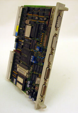
| No comment |
Description
6ES5246-4UA11 SIEMENS PLC NewProduct Description:
The IP246 positioning module represents the link between your plant and the programmable controller (PC). The standard function block FB164 is used for operating and monitoring, and FB165 for assigning parameters to the IP246. With the programming package COM246, you can generate, save and print machining programs and machine data. COM246 is also used to test the IP246 online with the plant connected.
Features:
Power supply
Power supply from system bus
+ 5V +/-570
Current input (without encoder supply)
IP246 -4UA (incremental)
approx 1.00 A
IP246 -4UB— (absolute)
approx 0.85 A
Load voltage L+ (front panel connection)
20...30 v
Current input (without encoder supply, digital outputs without load)
IP246 -4UA (incremental)
approx. 90 mA
IP246 -4UB— (absolute)
approx. 100 mA
Battery volt~ge (back-up)
2,7 .,, 5,25 V
Current from battery
typ. 5 uA; max. 250 UA
Power supply of position encoders via connector X4/X5
5 V position encoder
max. 300 mA per encoder
24 V position encoder
max. 300 mA per encoder
Inputs for digital actual position values
Input signals (per axis)
5 V differential signals ace. to RS422
2 square wave signals A and B and
(count and reference pulses from
the inverted signals /A, /B.
incremental encoders)
I reference pulse R and /R.
24 V inputs
2 square wave signals A and B.
1 reference pulse R
Input voltage signal O
-33 v +3 v
Input voltage signal 1
10.5 v ,., 33 v
Input current
max. 7 mA
Electrical isolation
no
Counting frequency
for 5 V differential signals
max. 500 kHz
for 24 V signals
max. 50 kHz
Permissible length of cable
max. 32 m shielded
Absolute value per axis (= number of digital inputs)
Input voltage signal O
-33 v . . . +3 v
input voltage signal 1
10.5 v ...33 v
Input current
max. 6.25 mA
Electrical isolation
no
Permissible length of cable
max. 32 m shielded
Analog outputs
Number of outputs per axis
1
Voltage range
+/- 10 V/2 mA
Electrical isolation
no
Permitted cable length
max. 32 m shielded
Digital inputs
Number of inputs per axis
4
Input voltage for signal O
-33 V 3.6 V
Input voltage for signal 1
13 v ...33 v
Electrical isolation
no
Two-wire BEROS with a power supply of 22 V -33 V can be connected
Digital output
Number of outputs per axis
20 v ..30 v
Power supply range
24 V
Power supply rated value
120 mA
Switching current (short circuit-proof)
1 000/0
Mechanical data
Dimensions (W x H x D)
Versions requiring fan
20 mm x 233 mm x 160 mm
Versions not requiring fan
40 mm x 233 mm x 160 mm
Weight
approx. 0.4 kg


