| No comment |
Your Position: Home
> Low Voltage > Pneumatic > 20mm Bore 10mm Stroke Compact Cylinder Double Acting with Rod End Female Thread Auto Switch/Build-in Magnet CDQ2B20-10DCategories
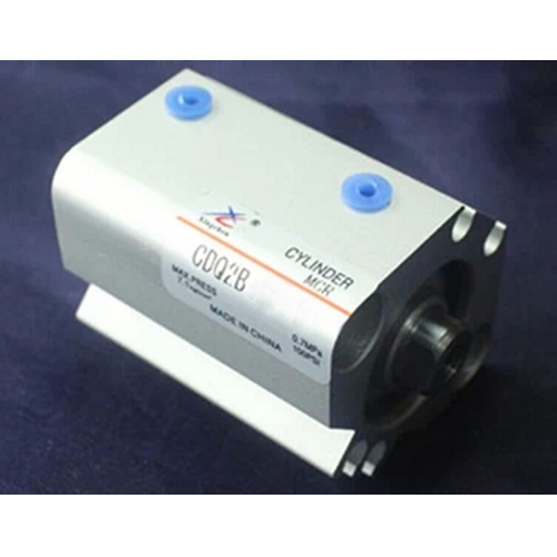
20mm Bore 10mm Stroke Compact Cylinder Double Acting with Rod End Female Thread Auto Switch/Build-in Magnet CDQ2B20-10D
Description
Compact Cylinder Double Acting CDQ2B Series
Specifications (Pneumatic):
Bore size(mm)
12
16
20
25
32
40
50
63
80
100
Fluid
Air
Action
Double acting
Single acting: Spring return/Spring extend
Proof pressure
1.5 MPa(15.3 kgf/cm2)
Maximum operating pressure
1.0 MPa(10.2 kgf/cm2)
Ambient and fluid temperature
5~60 degree
Rod end thread
Female thread(standard), male thread(optional)
Cushion
None
Stroke length tolerance
+1.0mm
0
Lubrication
Not required (Non-lube)
Installation
Through hole(standard), both ends female threads(optional)
Pipe size
M5*0.8
1/8
1/4
3/8
Travel switch/Magnet switch selection:
Bore size(mm)
Standard stroke
DIN
Double acting
Single acting
Magnet switch
12
5, 10, 15, 20, 25, 30
5, 10
D-A72L
D-A73L
D-A76L
D-A80L
D-F79L
D-J79L
16
20
5, 10, 15, 20, 25, 30, 35, 40, 45, 50
5, 10
25
32
5, 10, 15, 20, 25, 30, 35, 40, 45, 50, 75, 100
5, 10
40
50
10, 15, 20, 25, 30, 35, 40, 45, 50, 75, 100
10, 20
63
Not suitable
80
100
Component parts:
No.
Description
Material
1
Cylinder tube
Aluminum alloy (dia. 12~dia. 25)
2
Piston
Stainless steel (dia. 12~dia. 25)
Aluminum alloy (dia. 32~dia. 100)
3
Piston rod
Carbon steel (dia. 12~dia. 40)
4
Piston rod tube
Aluminum alloy (dia. 50~dia. 100)
Die-casting aluminum
5
Collar
Carbon steel
6
Bearing bush
Casting aluminum bronze
7
Spring
Copper
8
Plug seal
Alloy
9
Rod seal
NBR
10
Piston seal
11
Cylinder tube seal
Dimensions:
Model
CDQ2B12
CDQ2B16
CDQ2B20
CDQ2B25
CDQ2B32
CDQ2B40
CDQ2B50
Stroke range(mm)
5~30
5~30
5~50
5~50
5~50
5~50
10~50
A
31.5
34
38
37.5
40
46.5
48.5
B
28
30.5
31.5
32.5
33
39.5
40.5
Dia. D
6
8
10
12
16
16
20
E
32
38
46.8
52
45
52
64
F
6.5
5.5
5.5
5.5
7.5
8
10.5
H
M3*0.5
M4*0.7
M5*0.8
M6*1.0
M8*1.25
M8*1.25
M10*1.5
C
6
8
7
12
13
13
15
Dia. I
-
-
-
-
60
69
86
J
-
-
-
-
4.5
5
7
K
5
6
8
10
14
14
17
L
3.5
3.5
4.5
5
7
7
8
M
22
28
36
40
34
40
50
Dia. N
3.5
3.5
5.5
5.5
5.5
5.5
6.6
Dia. O
6.5 depth 3.5
6.5 depth 3.5
9 depth 7
9 depth 7
9 depth 7
9 depth 7
11 depth 8
P
M5*0.8
M5*0.8
M5*0.8
M5*0.8
1/8
1/8
1/4
Q
11
10
10.5
11
10.5
11
10.5
S
35.5
41.5
48
53.5
58.5
66
80
U
19.5
22.5
24.5
27.5
31.5
35
41
V
25
29
36
40
-
-
-
Z
-
-
-
-
18
18
22


